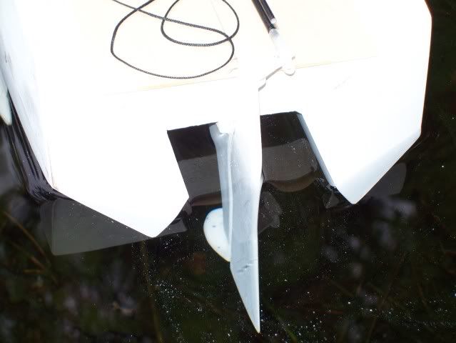
It has been some time since my last posting on this forum, a number of unfinished projects have kept me busy. so as I sat at my work bench and fumbled with an old rasor type hull, a very dim light came on in my head. by splitting the hull in half vertically, and flipping it over a couple of cat hulls came to mind. add a bit of width by forming a inner hull to accomidate radio gear but keep the overall width within the measurement box limit. A dual set of smaller keels are fastened to the hulls and project out to max width. A single rudder (also with ballast) has been centered , the aft portion of rudder rotates against ballasted part that is fixed to hull. The idea was to have less wetted overall surface in the water most of the time, increase stabillity both sideways and forward.


Hi Jim,
Interesting project and use for an old hull. Just one critique. You take pains to mention that the new “Cat” hull fits within the measurement box but then violate the moving ballast prohibition by attaching a bulb to the rudder. Is the rudder weight really integral to your design and if so then please explain?
Otherwise it is a good example of creative thinking outside the box, or I guess inside the box in this case.
Niel,
Jim said only the aft part of the rudder rotates.
I like it. :graduate: I have a similar hull drawn up from a few years back but this is more refined and further along. Please finish the build and let us know how it sails compared to more standard fare.
Jim -
perhaps optical illusion … Inside of hulls - are they parallel ? Boards below hull - are they parallel also? In photos you posted they look to be toe’d out in front and toe’d inwards near the stern. In the last photo this is distinct as one can see the “inside” of each of hull boards from front to back. “Normally” one would expect the front of those boards and the inside of each hull to be flat and not visible when viewed from in front. Basically, using your photos, it appears the inside of hulls are wider at bow than stern and same with the boards under each hull. I would have expected them to look like the rudder view - just the front thickness of each. If indeed the bow is wider than the stern, you may want to revisit the beam dimensions between hulls so they are the same at bow and stern. Comments only based on photos.
Thanks guys for the replys, I guess the last photo was to close and perspective gives the illusion that the hulls are farther apart at the bow, in fact they are 3/4" closer together than at the aft. this was mostly a compromise to obtain two deep vee hulls with a fair amount of rocker to point in the same direction.the photo below shows this and the fixed rudder skeg and rudder flexed over to left. here again the bulbs on the keels appear to be wider than the hull, but in fact are 1/16" inside widest part of hull. the rudder& skeg have been made longer and wider than keels, to counter some of the torque effect caused by the sail in a very short boat. the bulb might reduce some forward pitching and as it stands now, there is only 63 grams of lead combined. I’m not sure of the sail area / rigging or it’s configuration ,I will seal it up first and do some stabillity and self righting tests first. 
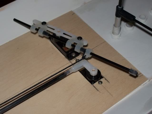
Just an update, hull has been sealed and tested for stability and self rights itself even with added weight on top of mast. servo / battery/receiver mounted for best trim as photos show, aft area of hull just entered in water. I made up a compound winch power lever from a long servo arm,(2) Du-Bro strip aileron horn sets, carbon rod and silicone tubing. the sheet attachment and the rod both slide in and out as required for extra power and extra travel. 


Your Stollery style sail arm lever should work ok but if you need more torque to pull in, consider using a normal single servo arm so that the ring holding the sheet can slide right up to the servo shaft where torque is maximum. This will shorten the arm by 3cm or so.
If you make the arm from spring steel it will give a little on gusts to relieve the servo gears from sudden shocks.
I reworked the winch set up so that more torque could be applied, it also gives a little to account for gusts and seems to be more adjustable. 


Hey Jim,
I like the “trombone slide” refinement to the Stollery Power Lever. How much more line take-up do you get from it and does that set up work when there isn’t much tension on the sheets in light winds? There would have to be the least amount of friction for the sails to go out all the way in ghosting conditions.
The (slide) travel as shown is 1.25" but this can be adjusted by set screw stop location. the control rod pins in the servo wheel have had the holes opened up and the holes have been chamfered to prevent drag, the pins rotate freely in wheel which seems to align them under even the lightest tension on the sheet. the key to this set up is to have the slides perfectly parallel thus preventing any binding. A light application of ( jig a loo ) makes the slide almost seem animated , so when the sheet reaches center of the arc portion ,the slide starts to more either in or out. the total sheet travel as set up in photos above is 3"
The past few weeks have been spent testing and tweeking, I have built a simple unirig that allows sail CE to be adjusted while maintaining step positon. three wheel collets have been soldered together, the center one has brass step pin , the outboard ones lock boom in place. the mast has been tensioned via back stay. the total rig wieght including sail is 24 grams. I may have built a larger sail than what was required for this boat and the lack of counterbalance (ballast) resulting in the addition of an extra 45 grams of lead added to the rudder keel. so as tested total boat wieght is 340 grams. this boat is very stable in all but heavy winds and performs better in very light breeze. with the water like glass and no wind recording on the meter, she seems to find wind and accelerates far quicker than my mono hull boat.I have yet to do a side by side comparision. I have flipped the servo location farther aft for beter tracking as she seems to like sitting back a bit in the water. more testing is required.


This is a really interesting project, Jim…noone has really explored the cat potential. I’m impressed with your engineering, too.
Side-by-side testing should be interesting…if it looks promising, maybe we could work together on a design for your next one?
Bill
Thanks Bill for your kind words and I would be very happy to work with you on improving the design. so far all tests have been beter than expected, I built a lower aspect sail for beter all round sailing although most of us like to fine tune with different sail plans. it seems less is more with this little ship with faster up wind and more control on down wind leg using a smaller rig. tacking is not like a real cat ,where the boat slows to almost a stop then rockets out, she is more predicable and carrys her wieght thru the turn and trims up quickly. she does have a fault however and that is she gives no notice of a knock down, I had one hull out of the water briefly in 10 to 12 mph winds only to go over as a result of my unskilled piloting.I think in the hands of a experienced skipper, she could be fast and fun.I’m curious to see if a longer rudder skeg & bulb would improve her control without affecting steering, also pondering a lighter ship made from balsa that would allow more counter balance while staying lean on overall wieght. as mentioned ,this is a old boat made of bass wood and split in half. the wife is coming out next test day to snap some photos/ video so you can get a better idea of how she sails.