OK, here’s a math question about laying out the jib.
If I’m given a luff length (hypotenuse = c), and the diagonal (altitude = h), how do you generate a right triangle out of those two dimensions?
OK, here’s a math question about laying out the jib.
If I’m given a luff length (hypotenuse = c), and the diagonal (altitude = h), how do you generate a right triangle out of those two dimensions?
OK, here’s a math question about laying out the jib.
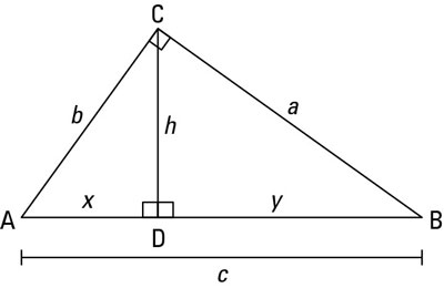
If I’m given a luff length (hypotenuse = c), and the diagonal (altitude = h), how do you generate a right triangle out of those two dimensions?
(this image is taken from another web site, rotate it to make a “jib”)
I’ll bet it involves sines and cosines. Never did understand that trig stuff.
I see two ways to solve this. If you are allergic to sines and cosines, I will start with the hard one. Pythagore showed us that a2 + b2 = c2.
Here, a2 = h2 + y2 and b2 = h2 + x2.
Therefore, c2 = (h2+y2)2 + (h2+x2)2.
Knowing that c = x + y, you have two equations with two unknowns. It is now a matter of plugging y = c - x in the big equation to find x. But this gets ugly.
The second way looks harder but it is much simpler to solve. We know that the sum of the three angles of a triangle equals 180.
Left triangle -> A + C[SUB]Left[/SUB] + 90 = 180 or A + C[SUB]Left[/SUB] = 90
Right triangle -> B + C[SUB]Right[/SUB] + 90 = 180 or B + C[SUB]Right[/SUB] = 90
And we know that C[SUB]Left[/SUB] + C[SUB]Right[/SUB] = 90
Therefore B + C[SUB]Right[/SUB] equals the same as C[SUB]Left[/SUB] + C[SUB]Right[/SUB] or B = C[SUB]Left[/SUB], which is the key.
TAN B = h / y (where TAN of an angle = opposite / adjacent)
TAN C[SUB]Left[/SUB] = x / h
Since B = C[SUB]Left[/SUB], TAN B = TAN C[SUB]Left[/SUB] and… drum roll… h/y = x/h or x = h2/y
We know that c = x + y. Again two equations with two unknowns. But this time much easier to solve as c = h2/y + y
I hope I didn’t screw up at some point as it is not easy to solve this over a text editor! Can someone double check this?
Link does not work
Guzz
I would get a big piece of paper and draw a large right angle on it. Then using “C” as a center, scribe an arc out into the area around “D”. Now take a stick the length of “c” and wiggle it around til the ends just touch the legs of the right angle and it’s just touching the arc you scribed. Draw a line.
Don
Don:
To much of a “fudge factor” using sticks 
Symont:
Thank you! I kept trying to go about it with Pythagoras and was getting no where (trying to simplify and solve was a nightmare)
So, solving C=h2/y + y, for y:
y=1/2(C+(C2-4h2)-2
or it works out as:
x=1/2(C-(C2-4h2)-2
Sweeeet!!! Math is so useful 
Been a long time since I ventured to post on this thread. Let’s say that I’ve made quite a few sails in the intervening several years, some of them okay, none of them especially good. But I’m not meticulous enough to make really good sails, it seems, having entirely too much “Tim the Toolman Tailor” in me (a reference to a sitcom character of a decade ago, for those of you not familiar with US television).
Recently I saw some professionally-made sails for Victorias that had vertical seams about 40 percent of the chord back from the luffs. I wondered about that, finally realizing that since building-in curvature with panels means stuffing extra material into the sail so that it has curvature in two perpendicular directions, the extra material may be just as well added by vertical seams as horizontal. That led me to build a set of Victoria sails, each of only two panels with a vertical seam at about 40 percent of chord. They are only so-so, but I think that is due more to my construction than to any inherent problems with vertical seams. I’ll see about posting a photo or two in a subsequent post, if anyone is interested.
Here are the pros and cons of vertical seams I’ve discovered so far:
Advantages: 1) It’s easy to get the extra material at the desired location along the chord; 2) it’s quicker to make one long vertical seam than three to five horizontal seams; 3) different materials may be used in a useful manner (if one thinks TriSpi is better for the luff and Mylar is better for the leech, for instance); 4) because there will generally be fewer seams, the relative widths of the extra material will be greater, and the assembly tolerances will be correspondingly more forgiving. I’ll add that these sails are also distinctive looking, since so few are now in use.
Disadvantages: 1) One long seam can be difficult to do well; 2) a vertical seam means that all the air flow will go over it; 3) a new seaming tool will probably be required.
It took me all of maybe fifteen minutes to make a beam-bending gadget along the same lines as Claudio’s Gadget, using a strip of wood and a board, both about 1 1/2 meters long, with two wood screws to hold the strip to the board, and a small wood block to wedge the strip away from the board where I wanted to add the most extra material. (My version of the gadget works in the opposite sense from Claudio’s; with mine, the curve is convex relative to the board rather than concave.)
I’ll go into more detail on my version of the tool and how I used it, if anyone is interested.
But the other reason for my posting is another realization I had about sail making. I’d thought idly from time to time about a computer program to calculate sail shape due to wind pressure, but only idly, because I’m way too lazy to do all the engineering review such a program would make necessary for me, and because the programming alone would be a lot of effort. That did lead me a couple of days ago to take another look at SailCut, though, and that brought about the second realization: if one is interested primarily in determining the geometry of additional material necessary in a seam in order to achieve built-in curvature, it is not necessary to have any more than a reasonably decent model for the sail shape, and that might be achieved by representing any intersection of the sail with a plane as a simple parabola. I believe this is generally what the author of SailCut has done, although he does not state what equation he uses, and it may be a little more complex than a parabola.
But the key is that a fairly simple equation can do a good job of approximating the shape any line inked on the sail might take up in use. Since the equation is fairly simple, we can calculate the arc length along the curve to any point, and this allows us to determine accurately the additional width necessary at any point along a seam in order to achieve a given camber at a given percentage of chord. That is the difference in lengths between the arc length of the curved line and a straight line between those two points on the sail is the width of necessary additional material. I believe this is exactly what SailCut does, and if the program author only included among its many seam capabilties one that was parallel to the luff, that program would already handle sails with vertical seams. (The “vertical seam” option SailCut now has is actually for seams parallel to the leech.)
It’s probably possible to fashion a spreadsheet to do these calculations, although it would be somewhat complex, as spreadsheets go. The initial sail shape part should be simple enough, but figuring intersections with seams in order to calculate the width of extra material at a dozen or so points along the seam might get tricky.
Mike Biggs
nice to see you back again, Mike. Welcome.
Dick
Can’t help with the spread sheets or formulae, but the idea of using vertical seams (parallel to luff) is something that’s been used on big boats for some time. Their usage tends to be restricted to mainsails where an in-mast furling system is used, the idea being that as the sail is furled the seams don’t ‘bulk up’ around the furling spar and distort the sail shape. The sails are very definitely geared towards cruising boats where shape is not such a big issue as with racing yachts and in my experience are very much a compromise shape.
I guess the biggest problem with the vertical seam is the interruption to the airflow over the sail and the loss of efficiency associated with that. Other than that, it’s an option definitely worth pursuing, perhaps resulting in a controlled experiment, two identical hulls, two identical sail areas, one traditionally made with seams running perpendicular to the leach the other with them parallel to the luff.
Just my few thoughts…
Regards,
Row
Well, there is one other drawback to vertical seams, sort of, relating to my statement that one of the advantages was more material crammed into the seam because there are fewer seams. You still can’t push on a rope, at least not very hard, if there’s any length to the rope. Soon as you try to force a little too much material into a seam, you get a wrinkle.
That’s probably why the only one making these sails, so far as I know now, uses multiple horizontal panels on the leech side of the vertical seam. This may be more to prevent that wrinkle than to build in any more material.
But the idea I really wanted to bring in was that of using the simple curve-fitting equations to determine the amount of extra material required in order for flat panels to approximate a sail shape with three dimensional curvature.
Mike
When I make sails I use horizontal seams, and on the main add 0.3-0.5% of the luff height to the luff; i.e. 3-5mm per metre.
This is tapered top and bottom,and gives the added fullness to the sail; when the wind gets up, and flattening the sail seems like a good idea, then tightening the backstay adds more mast bend- this works for me! 
Edward.
Oh, come on,
don’t any of the experts out there have anything to say about the previous post?
Edward.
For luff curve I simply bend a mast to the shape that it will be on the boat and cut that into the sail. I do my sail making with either Larry Robinson style round blocks or a Swede Johnson style elliptical block. I have wanted to make a claudio gadget, but have not done so yet. The one change I make for making repeatable sails on the Swede block is I put a mark at the high point on the block, then I put a mark on the seams a known distance from the luff. I align the two marks to make sure that the depth is what I want. On deeper sails the mark is ~3.25" from the luff, for flatter sails it is 2.5" from the luff.
I also use artist adhesive to hold the sails in place while taping instead of tape as Swede did. If I have to clean the block, I use lantern fuel which takes the adhesive off the block which is sealed with varnish.
I use the same method as Slotracer for the basic luff curve. I can add a lttle to that if I think it’s needed. I use elliptcal blocks but I put marks a centimeter apart starting at the front of the block. I can modify the shape of the sail by positioning the sail according to those marks. Moving the sail forward increases the draft and moves it forward. I keep records of each seam ie. Sail 10 Seam 1 Block 4 mark 3.
Don
I am on my Third set of sails for my IACC-120, using the gadget.
1st set - no compensation for mast bend. Poor shape but the boat moved.
2nd set - Too much camber up high. Material too heavy.
3rd set - Worked out well, understood my mast bend. Starting to understand boat tuning.
FWIW, I use 2 mil mylar (2nd set was 3 mil). I have a long plexiglas square rod I use for marking the luff curve. I struggle with the “Material Compensation” part of the curve, but I get by.
Surprising how long it takes to cut, tape, pocket, reinforce, grommet…
I am curious as to the effects of seem shape up high, how much to add…I have a big square top sail (NZL-92)
I will take a look at the maximum draft, as recommended and see if it can improve things. Thanks.
Any How, I started by reading this thread, and every time I make a sail, I start be re-reading
http://www.stirling.saradioyachting.org.au/sailmaking.htm
by Ben Morris. Just too much common sense in there, and I need to remind myself of the steps.
Mike
I find that the luff curve is the toughest part for me. Making up a jig to hold the mast in it’s working state(a slight curve) and then tracing it on to my sailmaking table has helped a lot. I can position the sail over the tracing to get a reasonably accurate basic luff curve. At least I know that at one backstay position the sail will hang nicely. I have a feeling that trying to push shape into the sail using luff curve is only marginal at best. Even using 2 mil mylar I don’t think there is enough stretch for the shape to move back very far. Most of the excess just seems to pucker right behind the mast. I have a gut feeling that any more than 2 or 3 mm more than the basic luff curve(my tracing) will get you into trouble. On my last main I just used the basic curve and if I want a fuller sail I slack off the backstay and let the mast straighten. It seems to work well.
Don
Me, too, at least mostly.
With regard to the gadget, it’s nothing more than a bent beam. Beams that are simply supported (engineering jargon for sitting on knife edges such that there is no resistance to bending provided by the support, much like a hinge [otherwise known in the same jargon as a “pinned connection”]) and have a single point load applied anywhere between the supports will take on a parabolic shape.
My first gadget used machine screws to set the spaces for two “loads” between two other screws that held the beam to the board, these latter two being just tight enough that the beam stayed in place, but certainly not locked down. Then the load screws can set the space by which the beam is lifted away from the board. My intention was to count turns of the screws, but in actual use I haven’t bothered much with that precision. It’s possible, though, if you know the threads per inch of the screw. 20 threads per inch means 0.050 inches per rotation of the screw. My beam bends outward in the middle, away from the board, rather than having the middle attached as Claudio does.
I also have used a broad-seaming block. While the block works okay for me, I decided I’d rather be able to really see just how much additional material was going into any one seam, which a gadget shows.
Mike
stll a huge novice…
my current claudio tool is mounted on a 2x4. the bendable edge is an aluminum Extruded L. about 36" long. the L nestles against the corner of the wood. also on the wood block I have an aluminum meter stick with the 50cm at the center, where the aluminum is screwed in place. I have 5mm spacer on each side that I can move around. and with the ruler I can set the spacers @ X cm from the center so its repeatable…
My next claudio tool will be anchored to a table top… with a new aluminum L and aluminum ruler. shoudlbe a more comfortable work station…
I just got a 36" plotter and I am hoping to try to feed sail material through it and print my panel diagrams directly on the material. Hopefully this will take out some of the error out of transferring from paper to sail and cut down on the time it takes. The plotter says it will accept films like mylar, but I don’t us emylar. so we’ll see how much it likes Trispi, and test 505 and dacron…
Novice? Yup, me too. I use plexiglass as my bender. Yo, Mike,a different take on the gadget, food for tought. Marc - I have cardboard sail patterns. Take a while to make, but I have never though of the initial cut as unreliable. Interesting.
The link I gave above also has a new analysis of the gadget, which is an interesting read. Ben talks about the differences between the tool, and a parabola…etc. Never comes out and says one shape is bad, but does try to get the gadget to be closer to the blocks for shape. I like using the gadget, but as I was thinking about building a block, I got stuck on what parameters to use, size and cord.
But then, the parameters for sailmaking. 5-2-2-10, or should I do 3-1-1-5, or should I do… The upper seem has me stumped. Then Max Camber…40%, 45%, 50%… I’ve been using 40%, sailing in 7-10 knot winds most of the time. I think 45% will be my next set. What to do with the top seam though…
For the luff curve, I need a better setup for lifting the clew and filling the sail to get my starting point for mast bend. Seems that by taping the clew to a bottle of wine to lift it works fine for a bit, but as the bottle gets lighter and lighter…
Mike