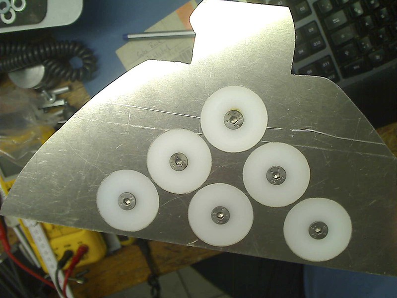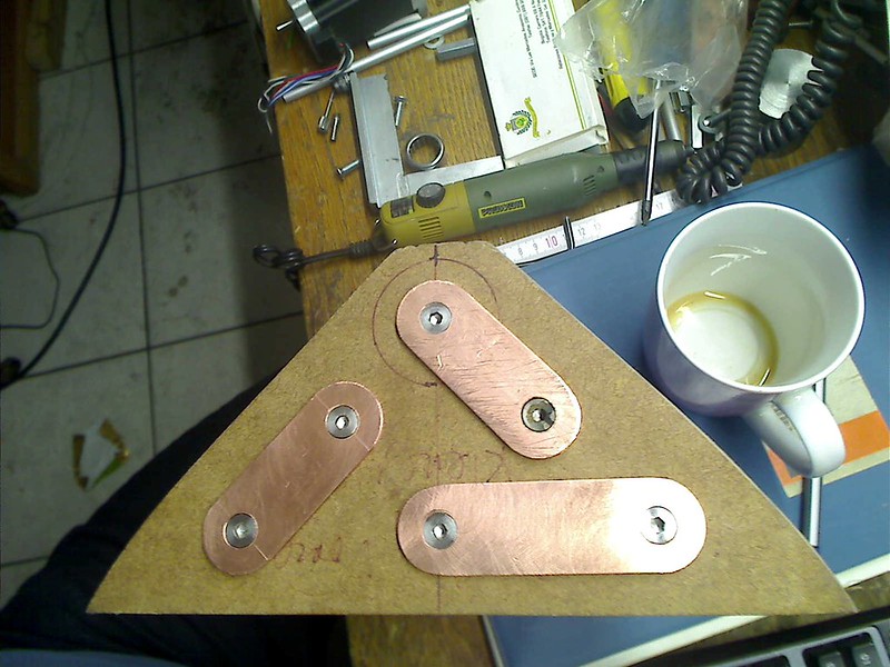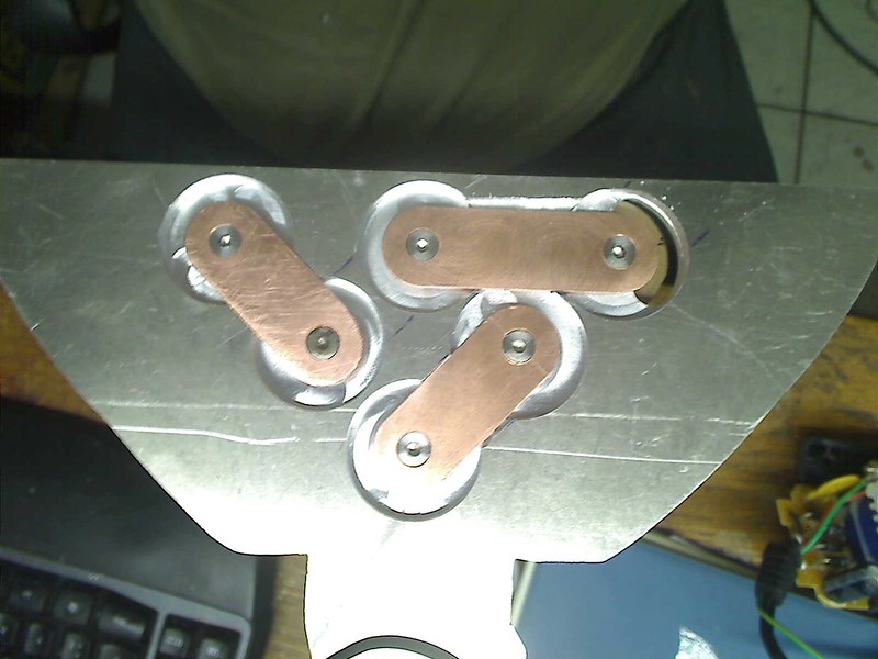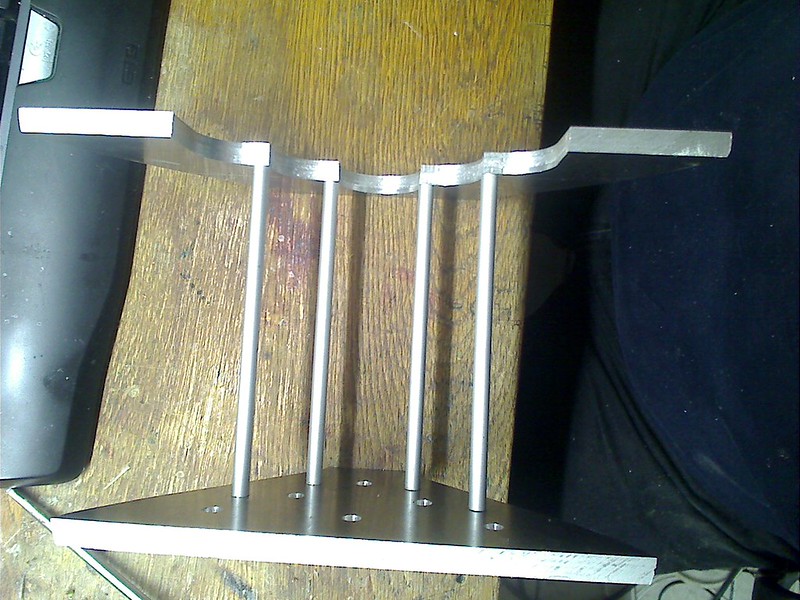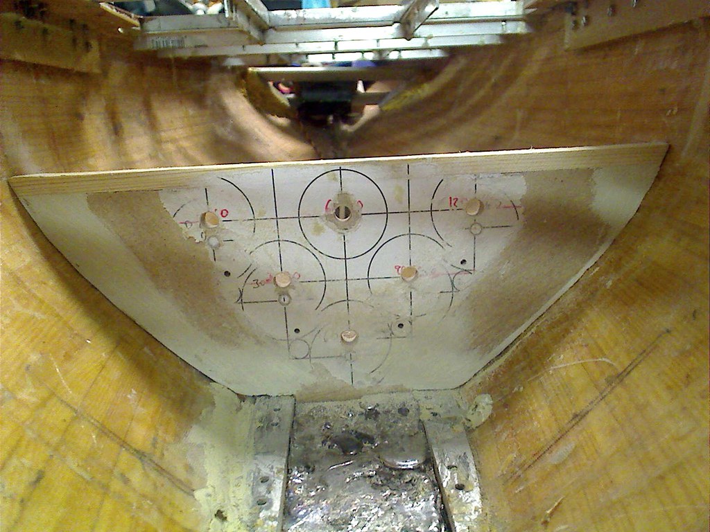
The same wall as before, but now from the other side!
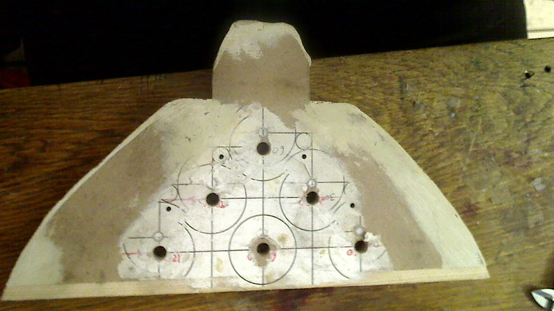
The same wall, but now finished to be used as a form to make the real aluminium version of it!
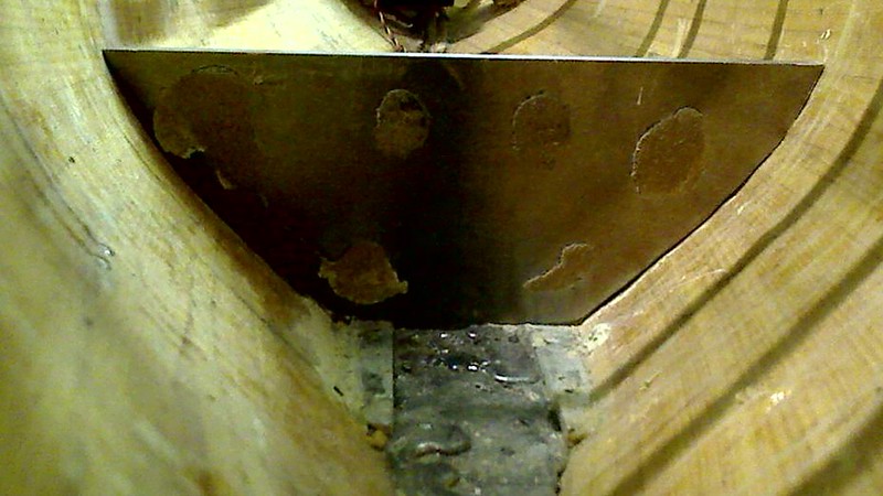
Here you see for the first time the aluminium version of the wall, still with leftovers from having glued the fale wooden wall onto the aluminium plate.
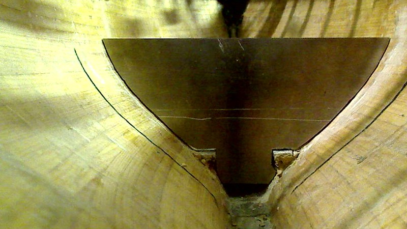
The same aluminium version of the wall from the other side. As you can see, at least for an untrained miller milling the aluminium shape of the wall having an wooden form glued onto the surface of the aluminium plate is far from perfect as can be seen by the gaps seen on the picture. Two main reasons exist for this! One is definitely the inability to mill the aluminium plate exactly enough to be shaped as the wooden form. The second even more important factor is the fact that the profile of a 10 mm thick aluminium wall does not have the same shape on both sides of the plate. The hull changes its shape enough over those 10 mm, so that the gaps are a result of this. It also proofs what I had expected, that I need to take extreme effort to shape the fake wooden versions of the walls at the very precise positions were they will be placed at the end! So manual work is required to adapt the shape of the aluminium wall to the hull shape in such a way that its upper border still is at its perfect place, so that the cover placed on top will be 100% parallel to the floating level of the sailboat!

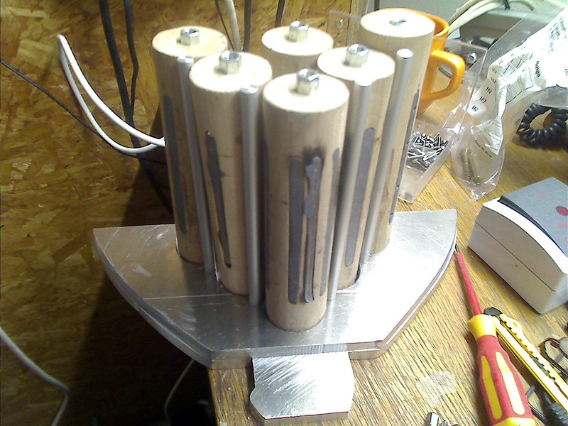
The same way, starting from the wooden fake wall i made the second wall of the battery cell compartment. To ensure that the shape of the second wall was taken from the correct position were that second wall would be placed within the hull I screwed the fake wooden battery cells between the aluminium wall finished first and the wooden second wall that was going to be the form to make its aluminium version shown here. Very critical, besides defining its shape by ensuring the 100% correct final position of the second wall, I also had to make 100% sure that the shape of the form in its final position would result in the battery cells being fixed by screwing its pole between both walls were 100% horizontal, means parallel to the floating level plane, that its upper border resulted in a perfect parallel placement of the cover when placed on top of the battery cell compartment. It took a lot of effort to accomplish this, make the aluminium version of it and placing the holes drilled for the screws for the poles of the battery cells at its right positions. As you can well imagine changing from the fake wooden versions of the walls to their final aluminium counterparts made it impossible to insert the real battery cells in the battery compartment. Short circuits with all their possible consequences would be the result! So what I did the was to make the aluminium solid tubes for which you had seen the 3 mm diameter holes drilled into the wooden walls.
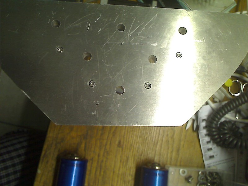
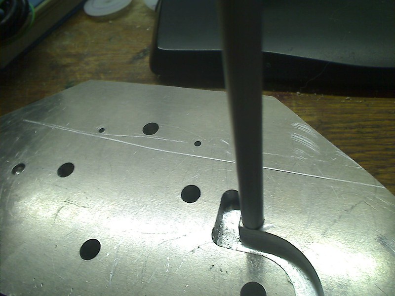
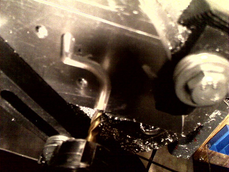
This picture shows on the second wall not just the holes drilled with the diameter of the screws for connecting to the poles of the battery cells, but also how the 3 mm diameter holes drilled for the M3 Allen cylinder head screws used to fix the aluminium bars over which the steel sheet would be bended that would form the rest for the battery cells in the compartment, at least for those hull side. as you can also see I have drilled holes with a bigger diameter so deep into the wall, that the cylinder heads fit into those cavities and lay below the surface level!
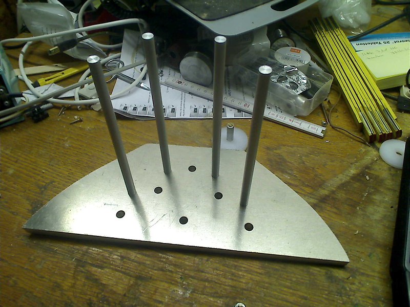
here you can see the second woll with the aluminium bars screwed into their position and the cylinder heads of the screws below the surface of the wall, so that the wall can rest fully on the desktop surface!
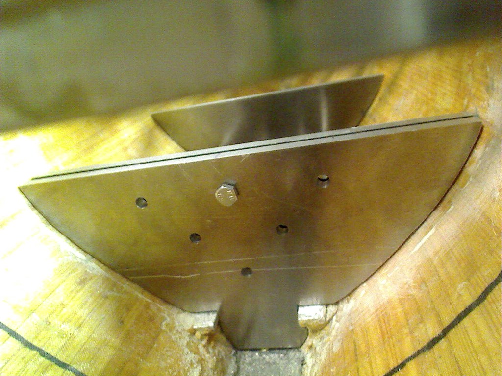
This picture of this contribution to my thread is from an earlier phase of the construction and shows both aluminium version walls, still without any holes drilled into them, but the first wall with a second wall directly fitted behind the first wall. Well, this requires some explanations and it will change some of the information supplied earlier to you! One of the objectives that I follow during my construction of the sailboat is to have most elements not glued into the hull or deck, but screwed into their positions. Well, the walls of the compartment consist of actually two plates!
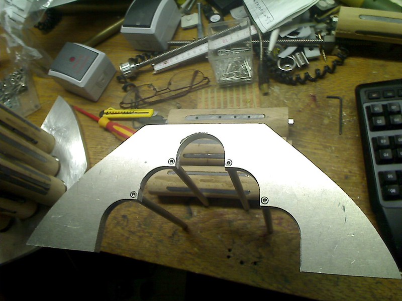
This picture shows the inner of the two plates that make up a wall of a battery compartment. You can see an aluminium structure that is perfectly shaped for the hull within the compartment next to the outer wall. Inside what has been eliminated is that part of the wall where the battery cells are and as you can see from the holes drilled for the M3 cylinder head Allen screws, the sharp corners not yet adapted to the shape of the aluminium bars screwed onto this inner wall. The steel sheet that will make the bed on which the “outer placed” battery cells rest, will rest and be screwed and glued onto this wall that will have the exact shape of the steel sheet. The aluminium bars will be screwed onto another inner wall of the same kind within the compartment and next to that second outer wall. What I still have to find out is how the length of the battery cells change when they get hot. As you well know, any material that increases its temperature changes its physical dimensions and so the compartment has to be long enough to have the battery cells fit within in case the batteries get hot, but do not yet burn! If they burn everything is over! Of course I have also already spend some thinking as to how I will make it possible for gas that might emanate from the battery cells to exit the compartment to prevent pressure from building up and eventually leading to an explosion!
I have postponed drilling the holes to screw both plates of a wall together, because for this I need to know where in the outer wall of a battery compartment I may have room to place those holes to be drilled in! Guess what, the inner structure of the outer walls of the battery cell compartment have a lot of stuff build in that I will present in my next contribution!
