I wish to ask how different RC boat clasess measure LWL in competition and how it is measured ?
Cheers Alan :zbeer:
I wish to ask how different RC boat clasess measure LWL in competition and how it is measured ?
Cheers Alan :zbeer:
Hmm, I wonder what started this thread off!
:rolleyes:
:lol: :lol: :lol:
ec12 class uses a waterproof box with an open top. a string across the front at the bow, and a string across the back at the stern and then measure the distance between the two strings they put a weight on the mast step to simulate a rig…
this link uses a clear polycarbonate box…
http://www.ec12.info/Initial%20Weigh-In.htm
Alan,
Did you read this bit?
“We increased up to 1040mm (+10mm) the real LWL to be sure that All our existing boat and future boats made using our official projects, will be in class rule,”
What do you make of that…?!
I have made a suggestion on the IACC 120 forum, just waiting to see the answer… But I have never come across a rule where the LWL keeps changing!
Cheers, Jim
Waterline is defined in the ERS, but the ERS does not say how to measure it. There are measurer handbooks that may cover the topis, but I do not have one. Usually the rules involving waterline length specify ‘fresh’ water. One challenge is to get the exact point on the hull as the meniscus gets in the way. This is not a problem for full sized boats due to overall scale, but can be a source of error in a model boat.
Two classes are very waterline dependent, the International A & 10R classes, as the waterline feeds into the formula and affects sail area. The 10R class requires a waterline mark on the hull at bow and stern and that is easy to measure. Then when the boat is floated, it cannot submerge the marks… quite easy to see.
From my past experience measuring boats, we used a float tank and floated a rule on the surface up to the waterline and read off a plumb line suspended off the overhang. A bit tricky to do and there is a small margin or error with repeatability. Then the LWL is calculated by subtracting the sum of the for and aft overhangs from the total LOA.
I like the current 10R method as the marks are measured out of the water, and then a simple float test to see if the marks are visible.
John
Hi Alan,
I could describe the the LWL measurement method used for AC/10 ( I was the Italian gauger and the rule is exactly the same of real ones) and it isn’t not so diffcult.
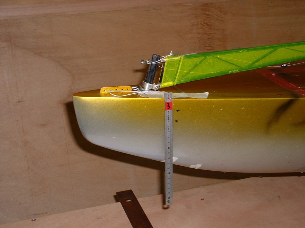
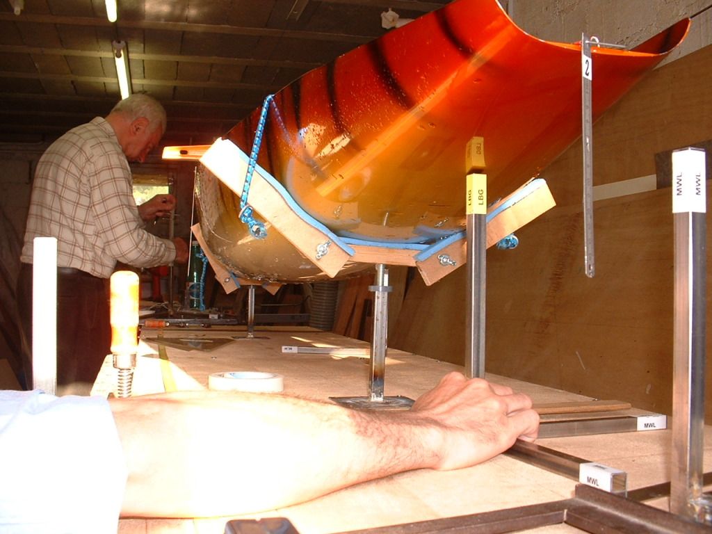
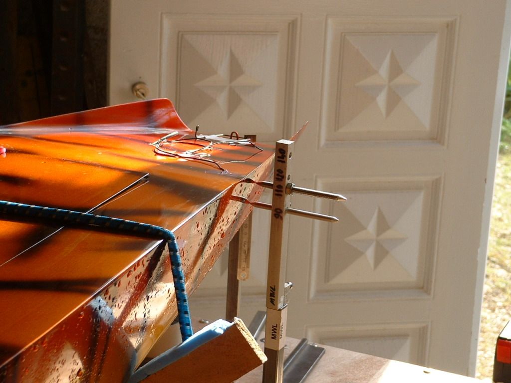
To avoid any problem due to water meniscus/surface tension on the quite flat hull extremities, are used any numbered metallic ruler placed on the side of the boat (see photo) quite perpendicular to water plane near the extremities of lwl and 2 near the maximum beam.
The accuracy of ruler placement isn’t important because the boat is placed in fresh water at measurement displacement and balanced in a measurement box and each numbered ruler is photographed by a digital camera identifying the ruler number and its intersection with water plane.
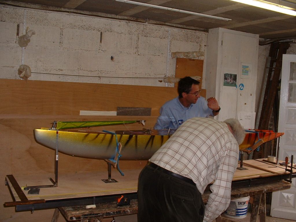
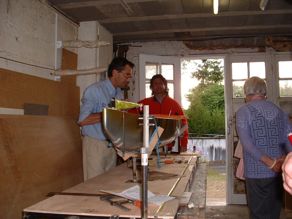
At this point the boat is disassembled and the hull is placed on the gauge table and, using photo data, it is aligned with the real LWL at the defined “std height” to the table.
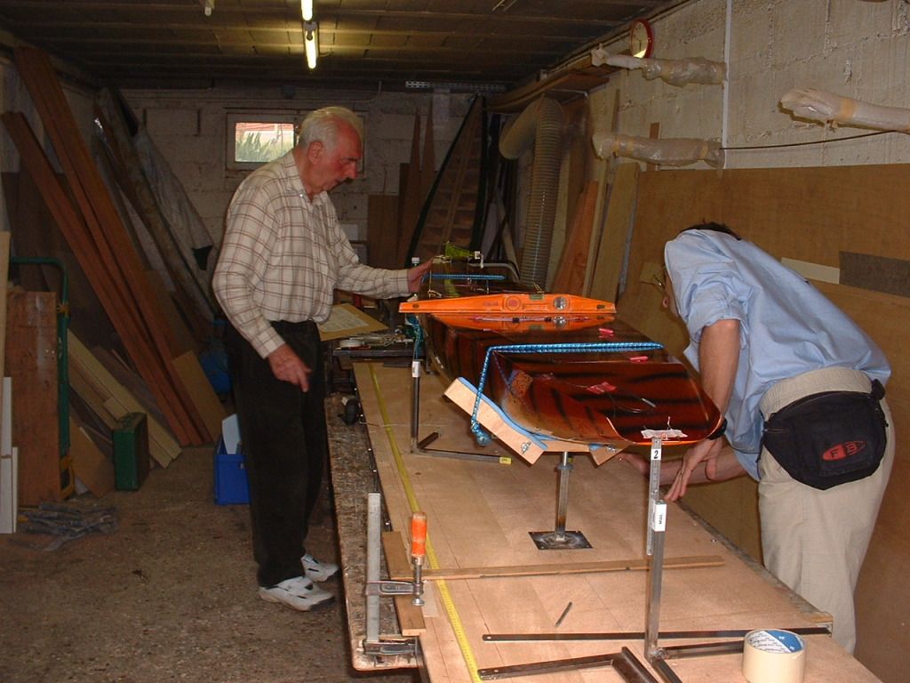
Then, with the std height gauge, are tracked the ends of LWL and rule length (20 mm over the real LWL for AC/10, 10 time less the real ones by linear scale factor). At the same time the ends of LWL and rule length are tracked also on the table using the std height gauge and measured with accuracy.
After this the rules measurement for the AC/10 are the same of real ones: fwd and aft chain development, ends of chain angles, minimum freeboard measurement etc etc .
Here the sequence that shows the verification steps
Hull preparation to go in measurement box
Example of ruler placement
Hull alignment on the table
Std height gauge to track ends of lwl on the hull and on the table
Aft chain ends and angle measurements
Fwd chain ends and angle measurements
As I had written on IACC Italian forum…
This method, a little bit simplified, could be used for any boats: speaking about the AC 120 It could be utilized placing , on the water plane, other marks added to the actual 2 mentioned in D2.2 (d): the Hull shall have two marks at the waterplane level, one in front and the other to the back. These marks are used for the LWL length measurement.
With 4 marks more, 2 near the front ones (one for side) and the other 2 near the back one (one for side) where the surface of the hull is quite perpendicular to water plane and there are quite no problems with tension surface.
I think that 60-100 mm from the hull extremities could be sufficient and the visualization of line it’s very simple. To put marks it is possible to use 4 ruler attached to the hull (with adhesive tape) in that positions and photographed with the boat in quiet water: removed the boat from the water using the digital photo it’s immediately possible to track on the hull the marks referring to ruler attached (no problem in ruler precise positioning because they are only local reference)
In this way, the gauger could clearly verify the true water level on the hull and the linearity of marks all around the hull and at the extremities of LWL.
This system is the same used on preliminarily lwl measurements before gauging on mine AC/10 and between mine lwl measuring and the LWL measured by the gauger there was less than 2 mm of difference on 1900mm of lwl… very precise!!
The true LWL length is always measured at the true intersection with water plane… but I think that using this method, no one of the actual ac120 verified by the gauger till now could be disqualified because this system is more precise and it is very probable that the actual measurements are “in excess”
In any case I think that it isn’t in the “spirit of the AC120 judge” arriving to use those systems: they aren’t necessary till now and I think that couldn’t be necessary for nest year… but could be used very quickly if necessary in case of arguments during the boat measuring from the judge.
Bye
Just little background, IACC 120 is going through some rules changes which I raised some questions as follows:
C 3.1 DIMENSIONS
With the Boat floating in fresh water :
LOA (with soft bumper included) 1150 mm to 1200 mm +/- 10mm
LWL 1000 mm +/ 3% (maximum 1030 mm)
LWL New Rule 1000 mm +/ 4% (maximum 1040 mm) +10 mm
Jim, I really don’t know what to make of changing LWL rules, I’m told some boats previously built have a longer LWL than the(1030mm) so now adding another 10 mm apparently rectifies the problem and brings “all those boats” back into class rules? …makes me wonder what I have been sailing against is all I can say.
What is now being proposed is that we take a photo of our boats and submit it for Autocad measurement…rather bizarre which brings us to the next notable new rule change.
D.2.2 Construction
(d) the Hull shall have two marks at the water plane level, one in front and the other to the back. These marks are used for the LWL length measurement.
Same as in John explains in 10R class, when the boat is floated, it cannot submerge the marks… quite easy to see.
Marc & John description of LWL RC boat measure seem logical and clear to everyone, thanks guys ! and Claudio V thank you for your AC 10 explanation and especially measurement of over-hangs, this is what Claudio D has been saying all along, however your LWL method looks cumbersome, sorry to say.
New Rule
(f) The hull must have minimum 40 mm overhang at the bow and 60mm at the stern (water tension included).
Rule (f) was done with the intention to preserve AC basic design of the class so some-one could not turn up with large IOM or V70 as example, but the words (water tension) were included in the new rule? as John rightfully says, meniscus gets in the way, I have since found out that this is a translation error so the water tension reference will now be excluded.
Cheers Alan
The method used for the EC12 is very effective and precise and simple to be implemented.
Some one shall be in charge to make the water tank equipped with the rulers as depicted in the above link : http://www.ec12.info/Initial%20Weigh-In.htm., but the described method is applicable ONLY for monotype hulls like an EC12 .
The point is different with the AC120 since anyone can design and build his own boat.
The main Rules says :
Marks on the hull and a balance can solve the verifications, before racing. water tank, as on the EC12…, but !!!.
The “problem” with the self made models, start with boats that are overweight above the 4500g minimum allowed, since it is assumed that these boats will sink more and will exibit a longer LWL !
There is very little to do to avoid “arguing” with measure of LWL once the boat is in the water !
Instead the weight measure is the only one that cannot be contested since the same balance shall be used for all partecipants, without any ‘fluid’ interference !.
One solution could be the overweight “time penality” applied to the arrival for boats from 4550 to 5000g with :
example : 1 second every 50g overweight.
A second solution could be to reduce the “BULB weight” to enter, either in the 1000mm lenght or 4500g weight !
Above 5000g , the boats are probably “self penalized” by their weights and wet surfaces anyhow !!!
Cheers
ClaudioD
You should remove lead from the bulb to remedy the LWL… Or take a sail area penalty
The 6mR class does this!
This could be a solution with the water tank and find the bulb/fin equivalent weight to reach 1000mm LWL.
The added weights, via a funnel and lead shots, container included, shall not be higher then 3000g in any case as per AC120 Rules .
The bucket shall be as close as possible to the CG/CB of the hull

Once done, the boat should be measured as a coplete boat on the balance and the total weight should not result below 4500g
The judge shall establish if a “time penality” shall be applied, either for “Longer LWL” above 1000mm or “Low Weight” below 4500g
In my opinion, Meniscus dimensions and Surface Tension measurements are not trustables and repeatables measures also because the meniscus lenght is variable as the slope of the entrance surface
ClaudioD
PS :
The RIG weight shall be added too with a simulation mass on the deck close to the mast step !
Hello,
When my J Class Endeavour was finished and sailing, I had not put the waterline onto the hull.
I took the boat to a very well known UK Club, they very kindly let me put the boat into their Measuring Tank.
The enclosed drawing shows the basic setup that they use.
The boat is placed into the tank and pushed upto the rear Fixed Stop.
Then the Moveable Stop is placed against the boat.
The Water Line length is the distance between the two Stops.
No meniscus problems - - no arguments ! - - - easy !!.
The two points were marked onto the Hull and the water Line was correct.
You are 100% right Claudio, however applying a time penalty is another continuous discussion that I hope we can avoid. Your other point on reducing weight is a good one !
Minimum total boat weight = 4500 grams to meet DWL to max 1000 mm (±3%)
a) Overweight hulls must correct (take-off) weight from keel fin/bulb, rudder or hull so total minimum boat weight meets DWL to max 1000 mm (±3%)
b) Underweight hulls must correct (add) weight to meet minimum weight limit of 4500 grams to DWL to max 1000 mm (±3%)
Clearly then if a hull is overweight, the penalty would be reduction bulb weight (if nothing else can be changed) would be most obvious thing to do.
JeeDee thanks, it is clear that the tank measurement method is most common method being used ![]()
Cheers Alan
Hi Alan,
The measuring aspects are not so simple as one may believe.
The AC120 hull do not carry the water line marked along the hull and therefore difficult to observe if the line is orizontal or not.
From the graphic in 2D I observed that 1 degree tilt is sufficient to modify the lenght of the LWL. In the case was 17mm out of 850mm, or 2% !!!
Some one suggested that the Speed of hour models are not dependant from the water line lenght , but may help a lot !!
To avoid “manipulations” is better to check carefully.
What it is interesting is that with the hull shapes recalling the AC Cup 2007, when you tilt the hull around the CB, the LWL is getting “shorter”. This phenomenon occurs often when running before the wind due to the wind pressure on the sails.
Is so true that many modelers, including myself, are adding some weight at the stern to lift up the bow, knowing that dynamically the asset will become “normal”.
To ensure that the 3D would expose the same observation, I picked up from the dust the female mould of the AC100-B that is very similar to many others of this AC type Hull.
I got confirmation that tilting by only about 1 degree or less, it is possible to “shorten momentarly” , the water line lenght and eventually get the “pass” when tested in the tank !. You got it ?


In view of that, the Rules shall adds some more “preventives” indications to avoid Bending of the Rules !!
Cheers
Claudio
Finishing with my 2 cents thoughts, I invite the readers to observe the LWL evolution of two differents boats models both pertaining to the same America Cup Class.
In this particular case I have choosen the AC120, but the concept is valid for the AC100 as well.
The difference is related to the boats developped in 1995 as the Black Magic and the Victory Challenge developped for the 2007 America Cup.

From the above sketch it is highlighted the fact that the Black Magic will increase the LWL lenght once the boat is tilting ‘longitudinnally’ under the wind pressure, while the Victory Challenge will loose LWL lenght for the same tilting.
The difference of the two LWL will be 36mm out of 985mm of the Black Magic that, btw, has 5mm shorter static LWL.
In other words the Black Magic will increase the LWL from 985mm to 998mm = + 13mm, and
the Victory Challenge will decrease from 990mm to 962mm = - 28mm
This is due to the different bow slopes entrances “angles” to the water.
For the Victory Challenge is 28° while for the Black Magic is low as 12.5°.
Obviously this game could be played with initial water level lenght of 1000mm maximum allowed by the Rules in static conditions !!!
“Lateral” heeling under the same “longitudinal” tilting not verified but supposed to produce the same effects, among the increase of the displacement due to sinking. i.e. average of +12% for 30° heel.
Are the two models accepatable to race togheter with the same standing classification ?
ClaudioD
Hi Claudio,
Just out of interest, if you were to stretch a IACC 120 of your design to a LWL of 1010mm @ 4500g - which I think should be about max to pass the new rule… Would you have less or more wetted surface? & how do you perceive the change in Prismatic?
These two characteristics really make a model fast or slow…
I’m not asking for a design, I would like to hear more your opinion on the potential advantages.
Thanks in advance,
Jim
Hi Jim,
Big question and not easy to answer !!!
I think that the yacht designer is spending his life to find “the” solution !
The starting point is anyhow the engine as the sails that shall motorise a mass trough the water as fast as possible for racing models.
For me , 4 elements are playing big roles, the hull form 20%, the sail form 30%, the tuning 20%, the fingers 30%
All reductions of resistances are welcomed. So working around the hull a gain of 1% in performances will be already a big achievement, but not easy !
Personally I will not profit of the maximum LWL allowed by the Rules to establish the static conditions.
Prismatic Coeficients, if they have the same sense as on the reals boats, then the choice will be connected with the weather conditions to be met regularly. Extreme weather changes are controlled by the proper sail surfaces options.
In my opinion, for our models the range may vary from 0.56 to 0.58 for an allround models. Over these extremes the justifications shall be dictated by extreme weather low or high.
For my places, my preferred PC is 0.57 +/- 0.2.
Models are sensitive to wetted surface, therefore I think that a design shall study the way to reduce that surface.
As everybody knows, a round surface will offer lower Wet Area, but…
The fashion consisting in copying the square forms, I dont think is paying off at model level, reconizing nevertheless a better heading in close hauled and with less drifting, the model developped by John Fries is a very good counter example !.
Above, may explain why I prefer to use short LWL statically knowing, anyhow, that it will increase for an AC type boat with overhangs, for two reasons as already shown in previous post and because the model will receive a vertical component force from the sails that will sink the boat in the water elongating thus the LWL.
Other sources for surface reduction are coming from the appendages and this is part of the game !
One of the most important points is the Balance of the hull !! but this I keep it for me.
The nice think of this art is that non one have found yet the correct answer to all questions and on the best options for a definitive design, otherwise the sailing model research would have finished centuries ago.
Finally your question : stretching the hull to get 1010mm at LWL , probably the wet surface will not increase, but need a check if the 4500g remain constant, instead the PC will increase if the main section immersed surface remain the same , all depend from the starting point !
One of my present tought is the one that consist to find the “ideal” place for the couple FIN/RIG along the LWL.
Have you any idea ?
Some famous architects questioned about, they told me : make two models with different options and tell us your findings
Cheers
ClaudioD
I would think the easy solution is to adopt the 10R style measurement. Put marks on the boat for the waterline, that is used for the measurement. The marks have to stay out of the water when the boat is floated at rest. If they go in the water, not legal. Once the marks are on the hull it is easy to measure to the edge of the marks.
Hi
hope somebody will listen !!!
Cheers
Claudio
Very nice summary Claudio and some food for thought, thanks again!
However, it does seem that his is now being completely ignored by the IACC forum since I pointed out they slipped up and practically admitted that they had to change the rule so one or more yachts would measure…
Well, I’m going to defiantly do some experimenting of my own, just need some time to go yachting!
Jim