Keel Mold

ok,

well as seen in my IOM build I am making a keel I did look at this site… http://www.fibreglast.com/product/mold-construction which has a ton of great info…

and I have been following claudios “esterel” build. I am pretty confident in my abilities to use a male plug to make a hull. this will me by first attempt at making a female mold and it will be a two part mold like claudios esterel so i can build a symmetrical keel

I still need to purchase the PVA mold release but I am having a brain fart…

with such a “thin” item figuring out getting the halves of the mold symmetrical around the keel and rudder is causing me some grief…

I know on the rudder I will have a rudder post one side and on the keel, I’ll have a threaded rod on one end but getting the center of the leading edge and trailing edge lined up such that my two part mold doesn’t wrap around the item and make removal impossible has me vexed…

http://www.rcsailing.net/forum1/showthread.php?5676-Making-a-Carbon-Fibre-Fin-Help/page3 i saw this Post 22

which gives me some idea…

I think I’ll need to insert some "pins or some other sort of a device into the centerline if the leading/trailing edges so I can easily make each side of the mold
I was really hoping to use fiberglass and cut strand glass/matting to make the mold rather than “plaster”

but like I said getting my head around making each halv and making them true halves is kicking my a$$ right now… I’m sure I’m overthinking it…

The halves do not need to be exactly half of the fin plug, as long as the two mold halves don’t have any undercuts, they will come apart. (actually, even if there is an undercut, the fin would probably slip out once the trailing edge was lifted from the mold)

Lay the fin on a flat surface with something like clay or caulk to hold it fairly level. Use a strip of plexiglass (get scraps from supplier or frame shop) against the trailing edge, placed vertically. another strip horizontally very close to the leading edge, hopefully close to the centerline of the fin plug. a thin bead of caulk of clay to fill the gap, using a razor bade to scrape excess off leaving it level and sealing the gap.

Apply PVA to everything. Make top half of mold (Gel coat, then fine fabric and build up mold with thicker or even chopped strand FG). Make sure you make it thick enough to avoid warping since it is so flat. I use epoxy for most molds to keep the shrinking/warping down

Pop it off of table surface, clean up edges and apply pva to the other side, and mold.

Before you pop mold halves apart, drill holes along the flange sticking out from the leading edge. Now you can bolt the halves together to align them after you have done a layup in each half.

The reason I do the plexiglass at the trailing edge like that is so there is a small gap in the mold to allow your fabric to stick out of the mold so any excess does not hold the mold halves apart. The vertical flange also adds a lot of strength to resist the mold flexing.
2536621923_5480e88d4f.jpg2550777611_f41d7e00f5.jpg

Brilliant…I knew there was something simple that I was missing…

I was thinking about using some towels under the keel using simple saran wrap to keep the epoxy off the towel. I like the idea of the plexiglass.

Hew, when you do the first side of the mold. the fin is flat on the surface. of the table. with the plexi on each side… when you do the flip side and leave the first half of the mold on the keel to ensure a nice symmetrical mold, i’ll need to “prop” the bottom mold near the leading edge to ensure the two lips of the mold on the trailing edge maintain their “squareness” to one another…

What are your thoughts on the adding in a tube or gap in the mold to allow for the rudder post and keel mounting bolt to extend through the the mold so it can be cast in place…

Hew is that your IOM fin?

Yes, I have a void in the mold so I can laminate a bolt inside the two fin halves. I leave the trailing edge plexiglass in place, or if it pops off, clamp it to the flange again before laying up the second side. Lay the whole thing on a block of wood so the trailing edge flange can hang down. It is not necessary for the perpendicular flange at the trailing edge to be exactly perpendicular, just eyeball the first layup.

I also mold in a couple of “Keys”, lumps on one flange, holes in the other, to align the two halves, not just the bolts.

That was a mold I used to make about 7 fins from. I used the fin itself to mold a fin box for each hull.

Or hold off until you can CNC mill your shape into a block of aluminum.

the CNC will come much later… that option was quite a few more “bills” I figure I need to learn how to break tools and screw up projects before the computer learns how to do it…

I have used a fin to make a mold for a keel box for my RG’s my RG is my learning station and then ramp up to the IOM…and I understand about making “bumps” to help the surfaces line up easier later on…

Marc,

I build my molds by making a parallel wooden box/trough the width you want your foil to be and double the length of the keel you need. Make up a metal squeegee that locks, over the front edge of the box, to the NACA profile you think you need - mix a load of thickened epoxy pour onto you trough/box and run the metal squeegee along the full length of the box. You will have to do a couple of runs over a couple of days. Once finished cut the box in half and you have a perfectly matched keel mold.

If you want a tapered foil use same technique but make sure the squeegee is locked onto the front edge. As it goes down the box the profile changes as the section narrows.

Hopefully you can figure out what I’ve said - but if not I’ll happily take a couple of pictures of my molds and post them.

Tony

tony, I saw this post by claudio

which is similar to what you do

Marc
What about your friend with the CNC at molds R-US ?

There are a few problems.

His machine doesn’t like my CADD Program and I’m not well versed on 3d CADD stuff yet…
He’s a bit busy at work for his 9-5 job…
He’s got some big reggatts he’s prepping for
I know he made a mold for someone else but did not make a copy for himself for me to borrow…

How about ordering/using a foam “wing” from any model airplane wing cutting services? They are not that expensive and IOM keels are big enough to make the job fairly simple… not like a footy for example …

You could laminate the wing and use it directly as a keel or use it a a male mold to make a female mold like hew suggested?

gio

I actually took a symetrical Heli Rotor split it added some material, and now I am in the process of sanding smoothing, fairing, ect…
if go here and look at post #23 you can see that beginning stages…

http://www.rcsailing.net/forum1/showthread.php?6805-Build-Log-IOM/page3

I have thought about using a “wingmaker” for my wing sail project. and I imagine it could be done on a keel /rudder as well, but with the foam being so thin for a keel or rudder I would imagine that it may make construction difficult out of foam.

once I get my mold made… I will use blue or Pink home insulation foam cut thin for my core. but i will rely on the mold to create the shape…

Claudio’s is exactly what I’m talking about

This is my method for making foils. I’ve built a mould which can produce one side of a fin or both sides of a rudder.
I will post a pic if my description is too unclear. All the components were srcounged for free.

This will produce a maximum 6mm fin with a camber at whatever distance back from the leading edge is desired.

Materials
-Plank of timber 500x150x30mm, nice and flat for a base

-3 sheets of roofing metal same dimensions, about 1.5mm (cut off scrap by my frindly metal supplies bloke,
still had plastic wrap protection on to keep the surfaces smooth)

-2 straight shims: strips of aluminium 500x10x3mm (cut by the same bloke)

-length of 500x90mm PVC downpipe

-500mm piece of timber - about 3x2 inch.

-2 pieces of ‘release film’ I have been using scraps of mylar sail 510x150mm (5mm overhang at each end, see below) Epoxy will not stick to it and it leaves a glossy surface.

-2 G-clamps

Method

Important: I recommend you have a trial run first and clamp the whole thing together before you start laying up to get the hang of it. Clamp in a newspaper or something.

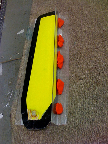
Glue one piece of sheet metal to timber base to make a very hard base surface. Take the 2 pieces of mylar and trace on the fin outline and mark on the maximum camber (thickness) line - say at 35-40% back from the leading edge, you will need to see this line at both ends to align the clamps on to so rule it fom end to end on the sheet. This is where the 5mm overhang comes in.

Tape one piece of mylar to one of the other two sheets of metal. Place on base and start laying up your CF or glass using the traced pattern as a guide. I used three layers of carbon: one diagonally (which becomes the outside layer), one length of unidirectional and one lengthways (after painting on a generous layer of epoxy first). Excess epoxy carefully spread and wiped out with a credit card. Place second piece of mylar film with fin outline on top aligned with the bottom piece, then last piece of sheet metal on top, trying to keep all the sheets reasonably square and flush with the base.

Now to create the camber.
Gently lift the metal sandwich up and place a shim under each long edge. I had parallel lines marked on the base and the metal sheets (and the mylar sheets) to line the shims up with. They want to be the same distance apart as the maximum width of the fin and keep them parallel.
Place the pipe along the max. camber line, insert the piece of timber inside it and clamp down the timber to the base. The clamp will fit into the mouth of the pipe and onto the timber inside. The pipe is to maintain a gentle curve and the timber is to help keep the pipe straight as you clamp the ends.
The clamps need to be just firm, not so tight that you squeeze all of the epoxy out of the centre. As you tighten you get a feel for how tight is tight enough. The metal sandwich curves in quite a satisfying way. Leave to set. Repeat and make a mirror image - don’t make two the same!

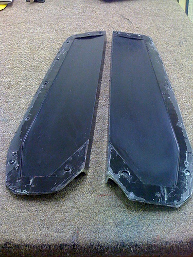
Out will pop a very strong and light sheet with a built in camber. Cut along the template pattern on the mylar and sand the edges straight. Peel off the inside sheets only! Resist the temptation to peel off the outside, leave it on the protect the surfaces for as long as possible. Place two halves together and tape leading edges together. Partly open out from the trailing edge and generously paint in epoxy on both leading and trailing edges, close, wipe and tape trailing edge closed. Rest on leading edge between two books to keep it straight.

Once set, partly tape off small end (leave a small hole for air to escape) and fill with epoxy. I mixed in some fairing filler to lighten it, not too much though, you want the epoxy to be a bit fluid to make it to the other end.

If you take the mylar off too early you can really make a mess of your nice shiny surface. Once set and you’ve sanded the edges to the degree you want - then pull the film off and behold!

For a rudder - both mirror images can be made in the one lay-up.

I’ve made two carbon fins, one carbon rudder and one FG rudder all of which are very strong. The fins, which tapered from about 90mm to 75mm, where about 120gm.

Hope this helps, Tony