Design by Modeling

Hi friends

I have been using my project, the Carina Sailboat as a “red line” along which I get in touch with a diverse spectrum of techniques. Nearly a decade ago I has discussions with friends about why electronics is not being used or accepted by naval modelists as one additional technology in our hobby. Lets make it clear! I am not talking about using commercially offered electronics as can be found in R/C transmitters and receivers, servos, motors and their controllers. Neither am I talking about the thousand of circuits that can be found in the Internet of electronics circuits that replace functionality offered by commercial products and that can be build applying the instructions made available with them. Also the latter to my believe is a first step into the right direction!

I am talking about seeing electronics not as a black box or as a “kit”, but as an additional technology that can be used to enrich our hobby. I like to describe this analog with the way we get to build our model ships! There are modell ready to fly or navigate or drive depending of which area of modelism you are interested in! Focus is to enable you to navigate out of the box! A perfectly legitimate and respectable position! On the other extreme you have those that after long research make their own plans and build a model based on the result of those research efforts. Same is true for electronics. Most have as a focus of their efforts navigating a sailboat, i.e., to compete in regattas and so the electronics are the means by which they can control their sailboats form the shore of a pond. This way the electronics are a black box, perfectly adequate for their objectives!

Mainly in motor boat models you find many aficionados that have the objective to implement as many functions as possible in their models and which either have deep pockets or set their expending priorities in such a way that they acquire often commercially offered often expensive electronics. Some of those aficionados extend into using hardware that is offered in the Internet to extend the capabilities of their basic commercial sourced electronic components. So, about a decade ago a friend of mine decided to develop a tutorial that enabled a participant to combine “modules” of electronic functionality from the electronic circuit drawing to their final electronic device that fitted their objectives. Was kind of analogous to the “lego” parts! Out of a reduced set of functions a hobbyist could create his own electronic design to implement something he had as an objective. This system, based on ATmel AVR microcontrollers, same can be achieved with the so called “PIC” controllers is lately been replaced a bit using Arduino boards and shields, which allow to save the effort of building your own electronic boards and combine performance, versatility and low cost to achieve a dramatically improved system, but still allowing the flexibility of a “Lego” system look alike flexibility.

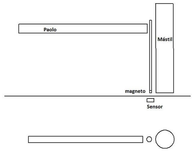
Having spend so many years along this path I decided some time ago to implement a sheet system to control the sails of my J-Class kind of sailboat that would allow me to change the length of the sheet by 8400 mm or approx. 330 inches:

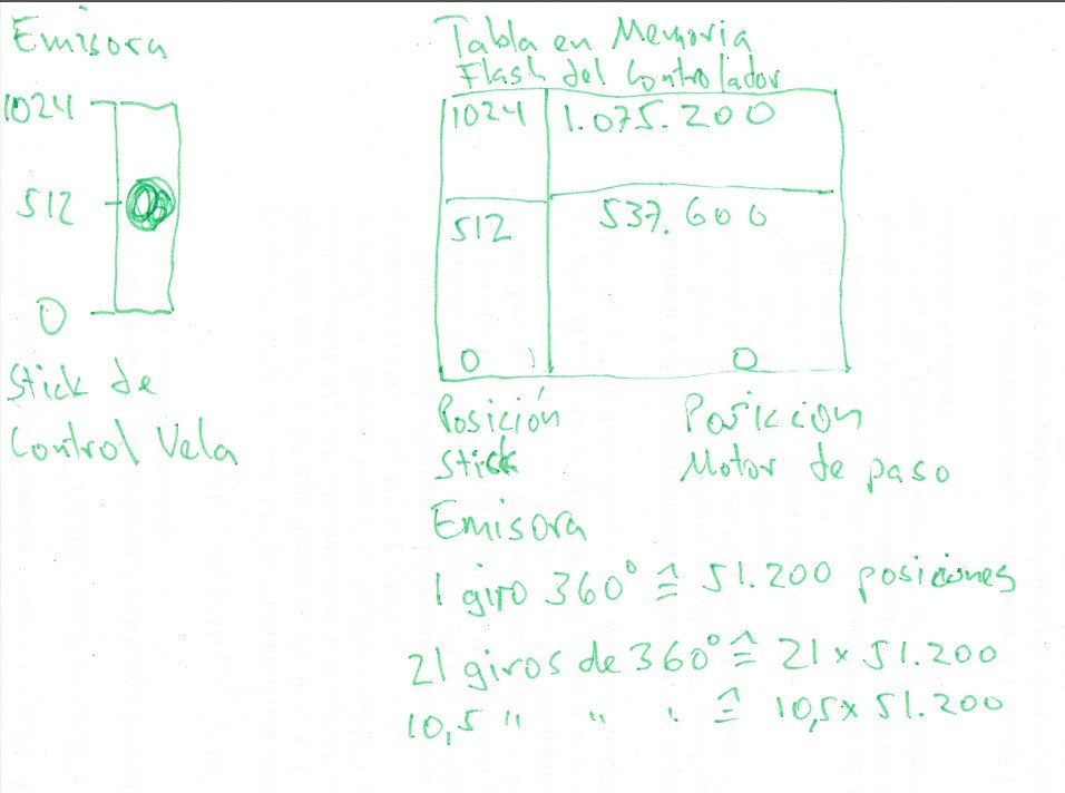
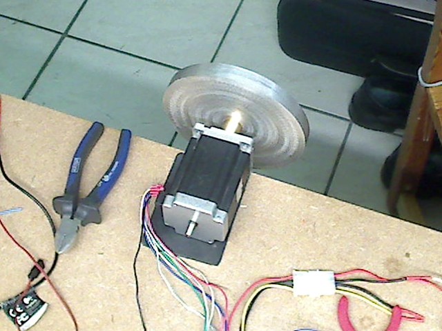
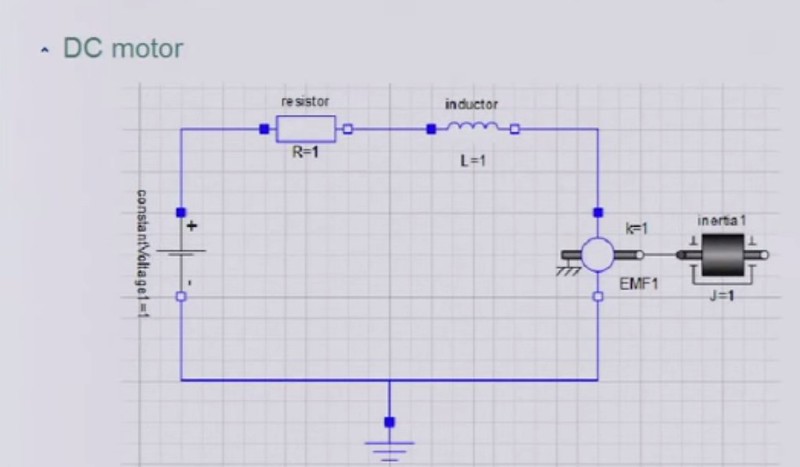
I decided to implement this system using a stepper motor to turn a drum with the sheet and have software running on a controller board to make only so much sheet available at any moment in time as required due to the position of the boom of the sail. So I track the position of the boom by using a magnetic angular sensor to report with at least 1024 positions for the possible 90° angle the boom can have between the center axis of the hull and the boom to either side. The stepper motor, with 51.200 positions per 360° full turn would choose a position that delivered the amount of sheet just required by the boom. The position of the control stick at the transmitter is equivalent to a certain angular position of the boom and so the stepper motor would not allowed to make more sheet available as required to limit the boom angle defined by the control stick position!

As often the details is where the challenge is found! So many very helpful sailboat aficionados reported their experiences and their opinions to my system, some even stating that my system could not work, due to the problems arising from the scale between an original J-Class sailboat and my model. Also reflecting of my system during my extend walks with our dog through the country side made me aware of challenges that would deeply impact the energy efficiency of my sheet control system and details about the operation of the system under certain conditions. So one of this continuous researches and investigations in the Internet made me aware of the technology called “System Modelling”. I was able to investigate further into it by studying the capabilities and limitations of a software combo called “Matlab and Simulink” and much later of another product called “Maple and Maplesim”. Finally I learned that also the good old software tool form Wolfram research, called Mathematica and a new product called “System Modeller”, offered similar capabilities to apply design by modelling techniques to my sheet control system with the goal to simulate and optimize the design and even to test against possible threats to its ability to work at all given by diverse model ship aficionados. So I started to reflect about my sheet control system with the new possibilities given by the technology of design by modelling and to try to find out what skills I would require to apply this methodology to the design of my sheet control system.

Lets summarize this the following way:

  1. My mathematics skills, frozen about 35 years ago when I studied mechanical engineering made it obvious that I would have to refresh and expand my knowledge, as all techniques related to this objective are strongly driven by applied mathematics. So no way i could use this technology without working on my skillset!

  2. Soon, after studying in detail what was required to get those skills by analyzing which courses would give me the required knowledge I found out, that today in the Internet you can choose from a relatively wide selection of offers, free courses such that the style of the teacher best applied to my way of learning. OpenCourseWare, a free offering of the MIT in Boston offers video recordings of lectures of the complete courses, videos of sessions were examples were solved for students as part of those courses, the complete written versions of the video recorded lectures, exercises and results and old exams that could be done under the same conditions as they would take place at the university. This way of learning is superior to that being in presence inscribed at a university and paying the awful rates that MIT i.e. demands from their students. Yo know what? I am having fun learning in this courses with no stress due to time, being able to repeat any part of a video recorded lecture until I grasp the content, being able in parallel to use google and wikipedia to dig in depth into any term, into information about any person mentioned or getting additional help to capture a topic. Also the recommended and suggested readings could be found in many cases for free as downloadable PDF files or as inexpensive e-books or kindle books.

  3. As universities of excellent quality in Germany are for free, I plan to collect the credits from the courses after I finish learning them in self study courses from OpenCourseWare or from german universities! This will also allow me to get additional information and study courses from after the bachelor degree! As mathematics are the core enabling skill set and tool set used in nearly all courses relevant to my objective to design by modelling using probably the software Mathematica and System Modeller and the description language Modelica I am using Mathematica to apply the mathematics I am learning to describe and solve the homework tasks. May be, if God or the devil do not call me too early from earth or as long as my brain is able to deal with the challenges of learning and applying that knowledge I might even get those degrees!

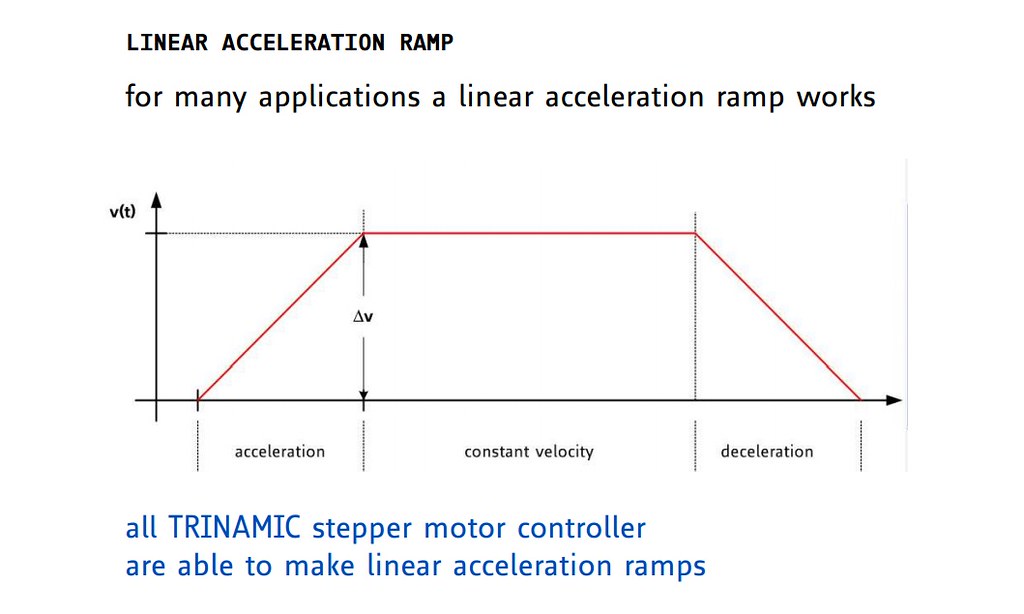
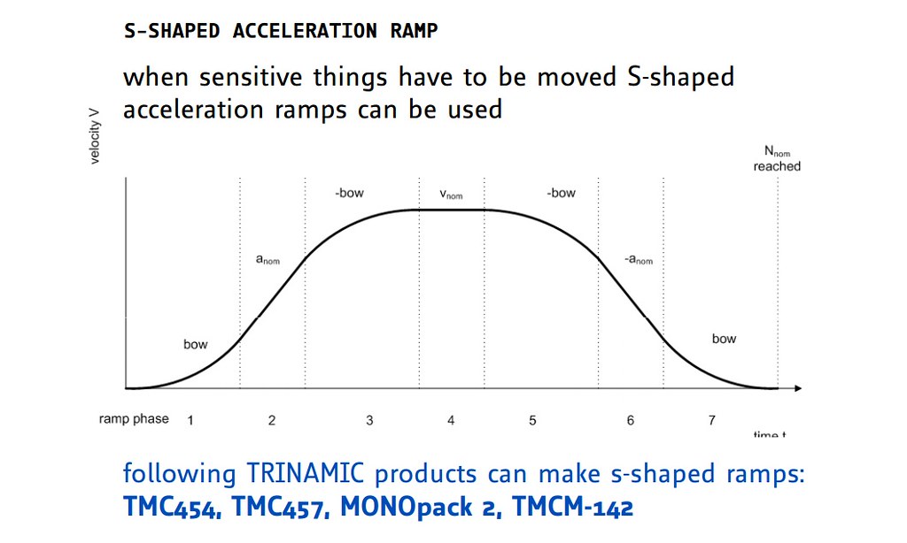
I have opened this thread and reported about what I have been writing here to share with you what might be considered to include 21st century science and technologies into our hobby. The opportunities rising from those developments in science and technology can have and have for me an immediate impact on experiments I do closely related to my project of a sailboat with this special sheet control system. I have not written about those practical and fascinating experiments and studies I have been doing and I am preparing to do, because already the concept about to include technologies and tools of the 21st. century in our hobby are hard to digest! Being very few that build sailboat models based on the results of extensive research, I expect it to be even far less those that my feel attracted by this new possibilities! If interest exists I would like to present the results so far about operating stepper motors, about the impact of most advanced parameters that can be controlled and played with in the operation of a stepper motor. About why a stepper motor is an interesting option to implement a winch using it and why my sheet control system aöllows to simplify extremely the mechanics involved in a sheet control system different from what is being used today.

But also research activities and a yearly competition about autonomous sailing robots about which I am working on writing some articles that reflect those contributions and the interesting opportunities those technologies presented in papers offer to be applied to our normal sailboats. The world of model sailboats has a lot to gain from 21st. century developments!

Hi Hellmut,

too long talk for me !

When I got at middle way I have already lost the first line !!

I would not care about the 1024 steps out of 90° boom swing. You just forgot the essential part of a RC sailing yacht where you sit at the shoreline of the pond and the boat is 100 meters far aways.

Under such conditions is difficult to adjust at the best the sail angle since you are not on board and remote speed detectors are not allowed.

Your electronics do not have pressure sensors spreads around the sail surface as well a computer program that decide where to stop the boom angle swing according to wind angle, etc .

At the end all what you tend to suggest cost a lot of money, just the contrary of what should be done …

Sorry for my 2 cents !!!

ClaudioD

No, no, Claudio, I do appreciate your response! Funny is, that even having tried to maintain the length of a text as short as possible, your response shows that you are missing key data and that you are running into the usual trap, trying to assume I have been foolish when dealing with the subject! Wouldn’t it be more constructive and useful to try to fill in your lag of information to understand why my approach makes sense, then assuming I am a fool?
So lets try to add and to respond to you as an offer to allow you to get an understanding!

The reason for my sheet control system is my need to support a change of length of the sheet, i.e. to control the main sail by 330 inches! No other system to my knowledge is capable to do so in a meaningful way!

The position of the boom is monitored and supplied digitally to a µCtrl. By using an magnetic angular sensor. Sof if the angular sensor offers a resolution of 1024 positions over an angle of 90°, this is equivalent to a change in length of the sheet of:

330 inches / 1024 positions = 0.3 inches change in length or 0.09° angle change of the boom! This is the accuracy the software controlling the sheet length has available!

The drum for the sheet, turned by the stepper motor has:

21 full turns of 400 mm or 15,75" each and 200 fullsteps and 256 microsteps per full step = 51.200 positions or 51.200 * 21 = 1.075.200 Positions to change the length of 330 inches or 330/1075200 = 3 * 10^-4 inches displacement per position.

By a similar principle, the position information of the control stick on the R/C transmitter is mapped onto an angle the boom is allowed to open in regards to the center line of the hull. Thgis way the software can control the position of the boom and the drum for the sheet not to exceed the limit set by the position of the control stick at the transmitter! The result is, that from the behaviour my sheet control system is not different at all as to the resulting behaviour of the sail control by the user at the shoreline of the pond from what everybody is used to!
But the difference is the ability to control 330 inches of sheet length in such a way that such a huge change of length can be managed what is not possible by any other means without the danger of having the sheet get trapped by any object on the deck, as the available sheet length is managed autonomously by the sheet control system according to the actual boom position! Also such a simple system, after a successful prototyping, allows for a much simpler and mechanically robust sheet control system and it is cheap compared to using winches for bigger sailboats!
Next comes the typical error when expressing an opinion without having properly understood a system proposal! Sorry for being so harsh, but I have sticked to my principles to respond open, respectful and honest and hopefully constructive!

  1. Length was apparently still too short for you to grasp the message, sorry!
  2. I hope I have been able to respond to your second issue regarding how worth the resolutions are, the user sitting 100 meters away! The resolution is significant for the system to operate but invisible to the operator. For this one it is identical to what he usually does!
  3. To define the adequate sail angle is and will continue to be the operators exclusive issue sitting at the shoreline 100 meters away! My system has no impact on this aspect! But it offer possibilities to enhance in the future for autonomous operation!
  4. You speak about that speed detectors are not allowed! by whom and when? But this is irrelevant for my sheet control system!
  5. My electronics have only and exclusively the objective to deal with implementing the ability to implement a robust sheet control system capable to implement a displacement length of 330 inches i.e.! So I agree that there are plenty of things it cannot do as normal sheet control systems can´t do either!
  6. So I hope you feel not offended by being indicated the senseless statements you write and which I am sure have to do with my inability to pass the message across!

I see forward to constructive responses and to questions that reflect the honest intention to deal with the toüpic I am presenting! Making it even shorter would even open the doors for more responses that start from assuming I am writing nonsense! I do not mind at all sincere critical responses as that from Claudio, but I try to respond presenting facts!

Hellmut,
I believe you need to come back to ground !
Read carefully the Classes Rules !
If you are so sure about your “1024 steps motor” idea, then start making it and search for customers …
ClaudioD

Claudio, good about my retirement condition is my possibility to spend effort without the goal to make money! The class rules are related to the competition of autonomous sailing robots, speak sail boats. My goal to use the design by modelling technique to design my sheet control system has little to do with the robotic sailing related issues. Nevertheless the articles in the proceedings present implementations of concepts that are enlightening and as such of interest to anybody dedicated to sailboat models! by the way, the stepper motor does not 1024 steps per turn, but 51200 microsteps per turn! It is the magnetic angular sensor who offers either 8, or 10, or 12, or 14 or 16 bits resolution per turn. The information from the sensors can be made available by different techniques. the quadrature encoding, a function supported by the respective quadrature encoding peripheral i.e. in the 1769 M3 ARM Cortex M µCtrlr. from NXP, is only available for up to 12 bits of resolution or 4096 positions per 360° turn. From there the 1024 positions of the boom angular position over just 90° result. For deciding when to change the stepper motor position when the booms moves at an angle smaller then the limit set by the user at the R/C transmitter requires the use of thresholds to decide when to move. Here it could be beneficial to get the angular position by polling the value from an internal register of the magnetic sensor. This value usually has a 2-bit higher resolution or 4-fold! I am planning to run tests to understand the errors of the magnetic encoder and compare the data from both sources within a magnetic encoder. I will do those experiments as part of the experiments with the stepper motor under load. Goals are additionally to understand the limitations of the magnetic encoder and the pros and cons of using the digital “A, B and Index” signals for the quadrature encoder versus the data available in the registers, to analyze the impact of the control parameters offered by the Trinamic controller ICs running the stepper motor load by external source.

Allow me to present my sheet control system a bit more in detail. The above graphic shows how a turn of the boom around the vertical axis turns a magnet placed at the bottom end of an axis that turns with the boom. This magnet nearly touches an opening at the deck, covered with a thin plastic foil to prevent water from getting into the hull. Below that plastic foil is the magnetic angular sensor, guaranteed staying dry just 1 to 2 mm from the turning magnet!

next you see a sketch about a table stored in the flash memory of the microcontroller. To understand the picture the following information. The position of the control stick at the R/C transmitter is reported by the receiver generating what is called a PWM signal were the length of time a pulse stays at logic “1” represents the position of the control stick. The resolution of this signal is much higher than even the most sensitive operator of a R/C transmitter can control the stick position. This pulse length is measured in the microcontroller by starting a counter when the pulse goes from logical “0” to “1” and the same counter is stopped when the inverse transition happens. So the numerical value resulting by the counter running ends up having a certain value when the stick is at one extreme and another when it is on the other extreme position at the transmitter. Depending on the speed with which the counter runs the resolution achievable digitizing the pulse length varies and in the graph I have simply assumed a value between “0” and “1024”, being 512 the middle position. So having a table stored in Flash that gives the equivalent of a stepper motor position to a control stick position, the software knows up to which stepper motor position the boom may oscillate freely, as it is closer to the hull center line than the limit set by the operator through the control stick position.

Now lets assume the position “X” is the current position of the boom, one of the possible 1024 positions the magnetic encoder can monitor. Lets assume this position “X” is closer to the hull center line meaning that the hull is allowed to move either to the position “X-1” if the boom is turning towards the center line of the hull, or it may open more by going to the position “X+1”. Now if I would set the length of the sheet such, that the boom could not open more than the “X” position it would never open more, as the sheet would prevent this from taking place.

So if I want to enable the boom to continue opening until sometime it reaches the limit position set by the operator at the R/C transmitter I need to supply more sheet so that the boom can continue opening. But I only want to supply enough extra sheet length so that it neither gets so long that is can get trapped by any object on the deck, but long enough so that I only need to have the stepper motor move a step forward providing more sheet as seldom as possible to save energy consumption. For this purpose I do define so called “thresholds”. This thresholds, when the boom turns over them and the software monitoring the data from the magnetic sensor realöices this, the stepper motor will turn a step either releasing more sheet or less sheet. To define the resolutions of the magnetic sensor and the stepper motor minimum number of microsteps and the values of the threshold around the current position of the boom “X” is therefor of utmost importance. This is one of the aspects the simulation will allow me to analyze. Of course those values can be approximated iteratively in experiments. But developing the models involved in the system design and dealing with their interactions might make visible to me other critical aspects I might not yet have realized.

This block diagram shows a top level view of the electronics in the subsystem in my sail boat model for the sheet control and it assumes that both the main and the foque sail have a boom and its angle is monitored by a magnetic angular sensor as shown above. This is why there are two identical branches in the diagram! Left most is the R/C receiver supplying the 2 PWM signals of the channels of the related control sticks of the R/C transmitter which are connected to 2 pins of the controller that have a counter and an interrupt related to them. So the software running on the second block from the left, an LPCXpresso 1769 board, keeps monitoring the control stick positions and maintaining the associated variable values in its flash memory. Should the operator decide to move the position of one of the control sticks this new value received is different from the one stored in memory and so the next LPCXpresso 1769 board is informed, which them updates the related variable value defining the maximum opening of the related sail! This cain of actions is fully independent from the execution of the sheet control subsystem and it only generates a minimum of traffic between the boards.

Now lets look in more detail to the vertical branch of modules and concentrate of the upper one, as the lower one is identical but in charge of the other sail! The boom of the sail, free to move as it wishes, only constraint by the ignorable torque of the magnetic sensing function and friction of the sheet and the boom movement, is monitored by the magnetic angular sensor that keeps storing the current angular position of the boom i.e. with 12 bits of resolution in an internal register readable by the LPCXpresso 1769 and during the same time the sensor is supplying the following 3 PWM pulses:

This graphic shows the 2 pulses “A” and “B” and how they are used to track the relative motion of the object being monitored by a magnet and the sensor. This 2 pulses allow a resolution of i.e. 12 bits for a 360° full turn or 1024 over an angle of 90°, to either side of the hulls center line! The third pulse is called “Z” of “Index” and only shows up once per full turn. In my sail boat the “Index” would be set such, that it is equivalent to the position where boom and hull center line are identical! This can easily be set during the build up of the boat, as the magnet could be turned manually until en LED, that activates when the boom is considered to be perfectly centered aligned with the hull center line. So the software would also track to which side of the hull the boom is! This would also allow to monitor the value of the variables tracking the boom angle and correct it if any errors happen. This limits error propagation!

Additionally to the tracking of the boom position by using the functionality of the quadrature encoder in the microcontroller the controller could read the absolute value of the angle stored in a readable register within the sensor. remember, such an ARM Cortex M3 microcontroller is running at at least 72 MHz, so reading the value stored in the register in the sensor would have close to no impact on other jobs of the microcontroller and in its controlling of the thresholds.

The same LPCXpresso 1769 board that interacts with the angular sensor of the boom and which receives updates from the other LPCXpresso 1769 board, by the way such a board just costs a bit more than 25,- Euros, will also instruct the “stepRocker” board that actually controls the stepper motor when it has to turn. The stepRocker board has its own ARM Controller with its own quadrature encoder and it has the ICs to control the stepper motor in a very sophisticated way, so that the ARM controller on board has little work to do.

So when the stepper motor is not moving, the electrical brake of the stepper motor holds the stepper motor in position, allowing to have the stepper motor being deactivated and only consuming absolute minimal power. This is the status in which the stepper motor will spend by far most of its time. Not doing anything and its electrical break, that prevents the stepper motor from turning when no tension is applied to it, will hold the stepper motor with no energy consumption. Should the stepper motor be requested to step, than the motor is activated, its parameters driven to appropriate values and then the breaks would be released. During all this time the stepRocker will be monitoring the position of the stepper motor and would ensure it does not turn without instruction to do so!

Here you can see the stepper motor with its drum, just in an early stage. The stepper motor and the drum represent the 2 blocks in the diagram to the right of the stepRocker board. To the right of it is the block representing a second angular sensor, mounted on the axis of the drum which will be cased and have the corresponding magnetic angular sensor build into the cage. Here the angular sensor is used to have a second source to track the position of the drum and its stepper motor. The sequential monitoring signals “A, B and Index” will be fed into the quadrature encoder peripheral of the µcontroller in the stepRocker to track the maximum 21 full turns the drum can make. The circumference of the drum is 400 mm, so 21 full turns deliver the sheet length change of 8400 mm or 330 inches! So the software can compare the values of the position parameter kept and maintained through the software of the stepRocker and monitor it comparing it with the data from the magnetic sensor!

I just want to end this contribution trying to remind you that the stepper motor controls its position with an accuracy of 51200 microsteps per full turn and that the magnetic sensor monitors and supervises the position of the stepper motor with may be up to 16 bits or 64 x 1024 positions and tracks the full turns additionally. Stepper motors are known to have high torque but to run slow! The stepper motor and the fact that just 21 full turns release or collect the 8400 mm sheet length means that the stepper motor is capable to do its job so fast that it would break all mechanics if it would run at full speed. The stepRocker and its successor, the “motionCookie” Boards have, tanks to the functionality of the Trinamic stepper motor control ICs important features to also address this and to only supply as much torque as the load at any time requires, adapting the torque and in consequence the energy consumed to the actual load. This impacts the energy consumption and the strength of the stepper motors required.

As with every prototype and due to technological advances my sheet control system is absolutely over dimensiond. But at the time I had to make design decisions I wanted to be sure not to under dimension any component involved in my sheet control system. Even as i have a pretty nice electronic lab, additionally to my mechanical workshop, where I can make my own boards, the LPCXpresso boards from NXP are so inexpensive that I have decided to use many of them for simplicity purpose.

Perhaps it is just me, but I am lost why so much sheeting line must be handled? For nearly all classes of racing r/c boats, there is a limit of 180 degrees - one side to the other, of boom movement. Most booms have the main sheet attached at least mid-length of the boom - although some actually are closer to the mast than others. It is a minority of boats that sheet from the end of the boom where the sheets must be long enough to stretch from the mid-line of the hull to the end of the boom ( or 90 degrees to either side of the hull).

If a typical boom is 30 cm in length and the main sheet is attached at the half-way location on the boom, then at 90 degrees (boom to C/L of hull) only 28 cm (+/-) of line would be needed if the sail winch is sufficiently strong enough to pull in the sail area being carried. If one were to use a 2:1 ratio to increase strength it certainly would only require a sheet length of 56 cm - certainly NOT 840 cm ! Again, very few model yachts currently racing use boom-end sheeting, so I fail to see “why” 840 cm of line (and movement) would be required.

As Claudio has suggested, you might want to review class rules to see what the maximum boom length is (based on sail area and length of mainsail foot) and I think you will find, you are searching for a solution to a problem that doesn’t exist in nearly 99% of racing r/c yachts. If we include multihulls, there simply is no way someone would spend the time to wait for a drum to turn so many revolutions, when hit by a gust and when they are trying to “dump” the wind from their sails.

Again, I may not understand why you think there is a need for a solution like this - as currently there isn’t many (any?) classes needing this much line to sheet in their mainsail boom.

My opinion only - I could be wrong… but you need to demonstrate “WHY” we need this much main sheet - THEN proceed to explain the electronics and engineering behind your proposed solution.

Regards, Dick Lemke
Minnesota, USA

Well, lets start giving you my thanks for the response! Of course here the explanation why!

This sail boat is not a boat belonging to a race category, but it is build imitating the sheet system used i.e. at the Endeavour. The first photo I presented in this thread shows why! I am repeating the publishing of this photo here as it gives the explanation!

This old photo of my model shows what the size of the model and its sails are! The boom of the main sail is 1 meter long. As you correctly state the sail can be opened 90° to both sides, so by applying the pythagorean rule, the length of the sheet would be approximately 1.4 meters. Now count how often the sheet goes from the deck to the boom, 6 times! 6* 1.4 meters = 8.4 meters! I hope this explains why I have the need for such a long displacement of the sheet. Because none of the traditional methods allow for such a length in a mechanically robust way and because of the high risk that the sheet might get trapped somewhere due to the limitations of the traditional methods for the sheet control system, even sail boats that want to to copy the sheet control system as used with the Endeavour, do actually sail replacing the sheet shown in the picture here with a single sheet to make R/C control possible!

I hope this answers your very justified question about the “why”!

As my sheet system is capable to adapt the sheet length fast enough, even faster than required, it is critical to operate the winch made using a stepper motor in such a way that the mechanics are not over stressed. Traditionally the speed profile of a stepper motor running from an initial position to a new target position will follow a trapezoidal profile, were acceleration and breaking follow a maximum acceleration allowed until a maximum speed is reached.

The trinamich controller board allows to change this trapezoidal speed profile by a curved one:

The result is wonderfully shown in this video, where a glass, half filled with water is once moved following a trapezoidal speed profile and once moved with s-shaped profile, see the difference:

[video=youtube_share;X4X_EUxqKEo]http://youtu.be/X4X_EUxqKEo?list=UU4SHA5_GAw1Wbm2T2NWpWbA[/video]

As I am sure you can appreciate, the mechanical stress on the blocks will be reduced dramatically! So my initial goal is to allow the sheet length to be changed twice form full length to shortest length and back to full length, 840 cm each time, in just 1 second. This should be fast enough to allow any change in sail position during any tack or jibing maneuver!

Hi friends, I again want to thank those responding, as those responses, specially when they are critical. Really one of the reasons I embarked into the adventure of the objective to use the technology design by modelling, were those critical comments. One of the comments claimed, that the main sail i.e. would not be able to open when the wind blows into it, as the friction between the sheet and the tubes through which the sheet is conducted from the sheet drum to the surface of the deck could not be overcome by the pull of the sail to the sheet. As a consequence the sail would remain close to the center line of the hull and so the navigating sailboat would fail to sail at all. To address this concerns, which the person claimed came from factual experience, is not so simple to study without having the boat actually navigating. When using the design by modelling technique I could have the friction computed, even adding other friction elements into the simulation. So the simulation has the charter to identify if and starting when just the inclination of the hull could overcome this friction. As a result of some other research efforts I have made, the main factor to the friction resistance against the move of the sheet in the tubes was not physical friction, but electrostatic charge building up between the sheet and the tubes that surround the sheet below the deck. One way to fight against this was using teflon tubes, another way, complementary used, was ensuring the sheet was wet and the dishwashing detergent. So of course I will start taking the friction element caused by electrostatics into the account, but I do plan to have a bit of detergent put into the case of the sheet drum and to ensure enough water is in the case, so that the sheet can be ensured to get wet.

I have already written about the need to use “threshold values” monitoring the boom angle to ensure proper operation of the system is possible. See pictures and text above. But that is not all I have come to realize as I keep reflecting over my sheet control system and over the constructive risks identified by fellow model ship building aficionados. 2 more issues have come into my mind that need reflecting and I am pretty sure that more will come up as I dig into the topic.

One issue is getting awareness of the torque load on the sheets during the diverse operating conditions. lets go case by case!

if the sail is open to the limit defined by the position of the control stick at the R/C transmitter, I have to decide if it is worthwhile, under energy efficiency considerations, to use an electrical break or the torque generated by the stepper motor. It is key here to keep in mind, that energy is only consumed by the electrical break, when the electrical break is released. You apply 24 VDC to have the electrical break release. If no energy is applied to the electrical break it keeps the stepper motor in its position! To make an educated decision about using an electrical break vs using the stepper motor itself not only the ratio of the time spend keeping the stepper motor in its current position, no electrical energy consumed as neither the stepper motor nor the electrical break consume energy at such a time. While the stepper motor is moving, and only during this time, the 24 VDC have to be applied to the electrical break, so during this time the electrical break consumes energy. Additionally the stepper motor is being operated, the reason why the electrical break is being released. Here the second aspect that has come into my awareness is the issue about how much torque load is working against the stepper motor.

This second aspect is much more complex to respond and as with any simulation, I will have to make assumption regarding the torque load and its ratio of time being spend under the different operating conditions to simplify the model and so to limit its computational requirements. But also certain assumption have to be made about how the time the stepper motor is being operate, a 100% is spread over the different load conditions. But here the simulation and its ability to identify minima and maxima will help to judge the assumptions. Just as examples allow me to present different load conditions of the stepper motor being operated, depending from the physical conditions!

  1. The skipper wants to have the sail open even more, i.e. to reduce the inclination of the hull due to stronger winds or gusts.

Here the full torque load as related to the pull on the sheet made by the sail will be in effect. The consequence is that the electronic control of the moving stepper motor will generate the required amount of current to flow through the coils of the stepper motor. The electronics I plan to use and with which i do my experiments allow to have them adapt the torque generated by the stepper motor to the torque load effective. So under the above conditions a relatively high energy consumption will take place, but I would expect it to last only short amounts of time.

  1. The boom changes its angular position due to the movement of the water in which the hull moves, which inclines the hull and in consequence might move lead to a turn of the angular position of the boom.

The load is basically “0”, so the stepper motor just adapts the length of the sheet.

  1. The boat turns its heading or the wind directions turns, here the boom will initiated a “longer” turning session".

Here the load is equal to that under point “2”, but the boom will change its angle over a longer time and over a larger angle. So the motor has to follow the free turn of the boom by adapting the sheet length to the actual changing boom angle.

I am taking as a example this case “3” to address another issue that is not yet properly analyzed in its consequences! Remember I mentioned, that the usual speed profile when the stepper motor moves from an initial position “A” to a final position “B” that is best described as being trapezoidal or “S-Shaped”. But as the monitoring scheme of the boom angle described above uses the thresholds to decide when to adapt the sheet length, every movement of the boom and in consequence of the stepper motor is just a series of single microsteps whenever a threshold value is reached. So the stepper motor will never ever, as the turning speed of the boom and the stepper motor in consequence are slow motion compared to the speed of the electronics, move between to distant positions “A” and “B” but only between adjacent microsteps positions! Only by analyzing and optimizing the behaviour of the stepper motor and the electrical break and the software I will be able to find an adequate first instantiation from which to start to identify conditions which allow different behaviours of the control circuit for optimizing the electrical efficiency. I am believing right now, that without simulation and experimenting with the control parameter values I will be able to identify a proper energy efficient way to operate the sheet control system!

But back to square one! I am experiencing and sharing with you readers of this thread the opportunities for actions related to our hobby the model ship building and navigating due to applying 21st. century technologies to our hobby! This, similar to the actions possible due to applying electronics to our hobby, prerequisite to the technology of design by modelling, open a new universe to our hobby, strictly related to our hobby, but addressing new areas! Same as some of us love to build static models, other competition sailboats and racing under the applicable class rules, even others like to build classical sail boats, our hobby is even richer in its variety. I have my affinity to electronics and now also to the technology of design by modeling, due to my professional background. My affinity to model building was placed in my heart by my father when he used to go with us kids to the airport to watch planes at a time planes were still more hobby look a like.

I confess, that I would never go on sailing in reality, as dying by an accident on the sea scares me much more that dying by a plane crashing! I also do confess, that I would not find pleasure in racing with sail boats. I also confess, that sitting at a border of a pond and having my sail boat controlled by R/C is pleasing, but only for a limited time! But dealing with building, with reflecting about options how to make something, to research what others do by reading threads related to our hobby and the topics related to it and finally by facing the challenges related to “out-of-the-box” thinking about ways how to make something on my model project is what motivates me most, what fills my thoughts while walking with my dog in the country side reflecting about a topic, that is what I really love to do. Finally, as the early Apples objective to evangelize to public about their technologies fascinated me, I also see a big satisfaction in evangelizing the community of model builders to consider to widen their view point from traditional technologies which are rich and diverse as nowhere else in the ship modeling community to consider the new technologies applied to our hobby. My first objective, starting about 10 to 15 years ago, was to promote electronics not as a black box supplied by some commercial or private source in the Internet, but as a technology, that reduced to a limited number of building blocks, like Lego parts, could be used to generated the electronics to be used as another tool box. This wish got even stronger with the 2.4GHz communication technology starting to replace R/C systems based on the MHz technology. Here marketing of the suppliers fooled the users to see this technology just as another way to make channels available to R/C systems and to ignore intentionally the consequences of the bi-directional serial data stream that it really is. Thanks to the chinese suppliers the R/C technology for the 2.4 GHz market segment has taken advantage of the dramatic cost reduction opportunities. But if we realize that 2.4GHz technology means that the transmitter in the hands of the operator and the receiver in the model actually both can transmit and receive data! If I see the premium prices the tradition suppliers apply to products that take advantage of this feature and if I see how cheap and easy to make are self build systems and how the “Internet of Things” is widening the offers at ever reduced prices, I feel we need to oppose to this misuse and open the box of inexpensive opportunities.

Design by modelling is in an different area another technology for which powerful tools are available for free or at reduced costs with tremendous opportunities. Wolfram and its “Mathematica and system Modeller”, Maple with “MapleSim” and “Matlab and MatSim” are the leading commercial vendors. I have decided to go with Mathematica from Wolfram as they offer relatively inexpensive versions of their product for private use, the other 2 suppliers are very expensive and student licenses limited to the time you are enrolled in a university. Also nice of going the “Wolfram” path is its link to the modelling language “Modelica” which is for free and it is an language and development environment very powerful to model our models of sail boats.

Now, I am pedantic and epic, no excuse! So my contributions to threads tend to be long, epic, because i tend to think around many corners and this reflects! But hey, thats me and nobody is forced to read my contributions! I very soon noticed that to use the technology of modeling for my purposes, my mathematical skills, learned and mostly stopped from being actively used some 35 years ago! They have eroded! So analyzing how to get the knowledge required, both from an electronical perspective to realize the circuits needed, as well as from modelling the physical environment and the mechanics involved in my sheet control system, I knew that this knowledge could be gathered for free in the Internet thanks to complete university courses available as videos of the lectures and exercise groups, lecture notes, examples and their solutions, OpenCourseWare from the MIT in Boston being an excellent example in english, similar offerings are available, but not to the same extend from universities in german and spanish speaking countries, 2 languages I am a native speaker of. Additionally german universities are for free, so that after learning the courses from the Internet I could even enroll and get my university degrees as a side effect of our hobby and the use of 21st century technologies. Its is even more encouraging! The fact that I as a nearly 58 years old person that is unable to work due to as of today 2 strokes and a couple of times my heart stopping to work due to cardiac rhythm problems due to medicamentation, which lead to have me implanted a pacemaker, was so well received at the contact person at the universities that I got access to their internal Intranet resources for free!

I believe, that as few person in our hobby have really made the step to use electronics as another technology available, even less will use the opportunities that the design by modeling offers for our hobby. But that is something that will be used in some future and that offers young people that get interested in our hobby to get in touch with technologies that offer professional opportunities for careers in their future. That is “evangelizing”!

Hellmut,

I think that you are on the right track regarding the use of electronics for model sailboats. I’m currently working on multi-hulls and trying to get them foiling and I think that for some configurations electronics will be required to keep the boats foiling in a stable manner. From shore with a radio controller the response time is just too slow and the resolution required for some adjustments too small. As you suggest there is probably quite a lot to be learnt from the model plane and helicopter area that could be applied to sailboats.

Jim.

Hi Mij
So one could think about Gyroscopes, Fixed Momentum Wheels, Microcomputer, Solar Array and Battery charge Controller , Webcam and associated transmitter and plenty of Arduino stuff and a gofer to put the boat in the water while the skipper stay home some miles always, behind his programmed computer, etc.
Of course all that is possible if the sailing boat will permit to load on board all materials needed.
How many would then agree to follow this evolution ?
Personnally I believe it is more important to find a way to avoid sinking of models as described in previous tread
CD

Hello Claudio,

I think your point regarding sinking boats probably highlights the reason that these technologies haven’t been taken up in the rc sailboat area. However, I think that it is inevitable that such devices will become more prevalent in rc sail boats. The reduction in size makes waterproofing such devices much easier, and the low cost makes them more accessible. In some ways it is remarkable that while virtual every other area of rc modelling has evolved to incorporate more complex electronic devices, rc sail boats have stuck with two servos and an rc controller.

It will be interesting to see where they are applied. My guess is that rc multihulls might be an early application as it would be quite attractive to use such devices to minimise capsizes.

Jim.

Jim,
some time sailing models are ahead more then what you think.
Just because I’m involved at the moment, you knows when the blade fin used on M Class or IOM or others many models was first used ?
CD

Thanks for enriching my world by responding to this thread. Writing about electronics, something i would consider 20th century technology field, speedily evolving to make 21st century challenges solvable, design by modelling is a technology that I would consider more a 21st century technology field. But both fields offering new possibilities for our hobby, they definitely are not more or less important than all the other technologies we apply in our hobby! They are just additional fields!

When you start dealing with self build and/or self designed electronics as a technology to be used in our hobby and when you get a feeling for what this technology makes possible when you dare to do out-of-the-box thinking that includes electronics to the bunch of equally important technologies that can and are applied in our hobby a whole new world opens in front of your eyes. And lets be explicit when I talk about electronics, I do not mean the products offered to our hobby by commercial vendors! Not that their offerings do not offer marvelous opportunities for new and more advanced stuff while filling the pockets of the commercial vendors! I mean electronics as a technology that can be used, not just buy buying “kits”, but by developing and building from scratch! And same as it is absolutely value free and equivalent to buy and sail bought kits of sail boats as it is to build such sail boats from scratch. Our hobby allows for many approaches to it, each satisfying and addressing different expectations of hobbyists!

Now if I hope you grasp that what I mean and talk about when speaking about electronics and design by modelling techniques in our hobby, I am addressing more the build from scratch perspective!

The design by modeling technology becomes relevant, at least to me, when using more and more the possibilities of electronics to implement functions, I got aware of the “power” to fine tune such designs. The example of the “thresholds” use in the controlling of the sheet system presented above is a pretty useful one! And the possibilities to fine tuning designs by modeling them and simulating them to study the impact of parameters to the goals of my designs makes very clear, at least to me, that here kind of a loop gets closed! Parting from a traditional sailboat that navigates under the control of a skipper on a R/C transmitter controlling a winch and a rudder, where the interactions of the skipper with its model and the model with nature, winds and waves, continuing into the abstraction and technology world of electronics and the optimization of design parameters of electronics and mechanics to the objectives of the hobbyist, the design by modeling approach soon gets you to include into your thinking and design the influence of the environment in which the model operates. Wind, waves and their impact on the sailboat and its navigation and the mechanics of implementation also bring the physical environment into the equation!

For me, I have decided to update and develop my knowledge, by studying courses i.e. as offered by the MIT for free in their “OpenCourseWare” offering. So first I looked into the field of electronics by looking into the career path of studying electronics for Bachelor and Master. Control technology being presented in depth really only as part of the Master of electronics. Soon I realized that without a profound knowledge in Mathematics not much could be achieved, neither in the “design by modeling” field nor in the many courses that make up the bachelor and even Master in electronics. But I found out that thanks to the Internet and to advances in the field of mathematics and its teaching That I could be fascinated by studying the courses that make up the Bachelor in Mathematics and by doing so I could really start to benefits form the power offered by tools like “Mathematica” and “System Modeller” by Wolfram, “Maple” and “MapleSim” by Maple and “Matlab” und “Simulink” by Mathworks to give some examples of those tools and of the language “Modelica” that is a programming language used to generate “Models”. Here I heard and started to learn what “Causal” and “Acausal” models are! So studying Mathematics become an obvious enabling study! But here I also learned by getting in touch with german universities, by the way for free too, that in the study of mathematics the applying of mathematical knowledge taught to describe and eventually solve “real physical”, financial and so one topics was part of the curriculum! Here our hobby and the use of the knowledge as part of my effort to use and apply design by modeling principles for my sail boat project made it evident that also the study of “Physics” made sense. So in this first half year since I embarked into this enterprise I have spend tons of time trying to understand the impacts and possible consequences of pursuing my goal to apply design by modeling to my sail boat project “Carina” as presented in this forum, I have basically worked on identifying the interdependencies of the diverse knowledges expressed in “university courses” that might be beneficial to my goal, to acquire the literature, the lecture notes and so on of those courses and to identify which offerings available in the Internet would be required to as a bypass effect collect those university degrees! Physics is definitely in the scope and when you study what a course of experimental physics and theoretical physics as teached in the first 2 years of the bachelor in physics copes with, you find out that it is basically teaching you what the physical world in its widest sense impacts our sail boat and as a consequence influences our model pursued as part of design by modeling.

I plan to present the proceedings literature about autonomous sailboat conferences from 2008 until today, another valuable resource!

So please, present eventual ideas you might have to apply either self build electronics and or design goals that you would like to consider for the use of design by modeling!

Hi Friends, I am aware that very few follow what I write and even less are willing to really drill into the understanding and eventual use of the stuff for themselves! Hey, no problem! May be any day in the future somebody finds the thread useful, ok, my be not, fine too! Still so I do offer the opportunity to follow my activities in my project of a sailboat, the Carina!

In my studying to refresh and update my academic knowledge I am advancing slower then I had expected. Recently I got to a point where my brain decided to stop learning and did so so strong, that I could not even just sit in front of the TV set and watch passively any offering. So like a sportsman after having injured himself needs to train to fix his problem and get back to his former performance levels, I need to continue exercising my brain to have it overcome the damages caused by my cardiac rhythm problems and reorganize itself! Hey, a fine challenge!

Walking in the countryside with my dog and reflecting about my sheet control system I discovered mayor flaws in my thinking so far, so that as a result I have discovered 3 issues! Well, one of the reason I am learning to apply the technology of design by modeling was to advance my understanding of it and in consequence being able to identify new threads to my objectives!

The issues are a consequence of having developed the concept of using threshold values to adapt the length of the sheet while the boom of the corresponding sail either oscillates or is opening or it is in the process to change its position from one side of the hull to the other one! If I do not discover a way to have the electronics being able to identify what kind of movement, speak change of angle to the hull centerline is taking place, my electronics can only take into account the information about the actual angle position the boom is having or passing. So any turn of the boom, for what ever reason for the sheet control system is just a movement that reaches a threshold which causes the sheet control system to deliver the sheet length related to the next angular position! This means any turn of the boom is just a sequence of moves to a neighboring position! This means I will never have the system face the task to have the length of the sheet change to be form a current position to another more distant one. So by the means the electronics offer I can never take advantage of either a trapezoidal or a “S-shaped” speed profile.

My system gets from the magnetic angular sensor monitoring the boom position 2 kinds of information! One is the quadrature encoded 3 PWM signals “A”, “B” and “I” which is fed to the appropriate 3 pins of the quadrature encoding peripheral on chip of the LPC1769 ARM Cortex M3 Controller monitoring the incremental angular position data. Here the hardware in the quadrature encoder peripheral and the functionality of the CMSIS library element in charge of the peripheral might be the only capable to supply additional information that I might be able to evaluate! This might make it possible to have the additional intelligence and data available to identify and implement speed profiles. The second kind is the absolute angular position information, for which the Controller needs to read registers within the sensor and that so far I have planed to use to implement the threshold monitoring!

Closely related to this is the question how many clock ticks, equivalent to a certain number of instructions the microcontroller can execute while the boom moves from one of the monitored positions to the next. Will their still be enough computing time available to implement and run the required software? First estimations allow me to assume yes, by far!

The third finally is related to the fact that a too fast rate change of movement of the sheet can over stress the mechanics of the sheet system!

For me this issues represent on one side my achieving the objective to develop an continuously improvement of the understanding of the system, but also sets objectives that I can study experimentally

Hi friends, while I am still not happy with the peed of progress in my efforts studying the academic courses I have been advancing in my research work regarding setting the foundation to apply those 2 software tools from Wolfram, Mathematica and SystemModeler and in identifying ways to get hold of stuff to start investigating experimentally. To give the background information about why I am pursuing certain activities I will introduce you to the subjects. Allow me to advice you upfront that that background information I will deliver and which is key to apply the “Design by Modelling” methodology for my sailboat model, the Carina is going to culminate into what i am expecting from 2 block of stuff I have purchased and received today!

First starting to explain that the software Mathematica is one of the mathematical tools with the highest reputation in the community of researchers and academic communities and offers a license for none commercial use that is affordable. This is definitely not the case with some of the other tool vendors like those that offer Matlab or Maple. For the purpose of design by modelling Mathematica is used with SystemModeler a tool specialized for modelling and were Wolfram is trying to catch up by supporting the design ob objects for the model supporting the use of Modelica, same as does Maple with MapleSim, the ecosystem for this toolset is much more advanced for the purpose of design by modelling compared to the tools offered by Wolfram! lets very much simplified, that the mathematics to be used are basically of 2 kinds. One is symbolic the other numerical.

Lets look at the equation for the sin: Y = sin(x):

What you on this image is a plot of the equation entering numerical values that result in a value for “Y”. So if you go from X = -2 pi to +2 pi in small increments you get the graph shown above! This is numeric. If you keep the symbols for the entities and manipulate them mathematically without entering numeric values you are closer to what is called symbolic mathematics.

Know let us have a very superficial view onto what is SystemModeler used for and in that context explain what are causal and acausal objects used in a model by taking a very simple example of a circuit that feeds a DC motor and generates a mechanical rotational movement together with a force called torque!

This very simple model shows a battery feeding an electric circuit that reflects the electrical behaviour of the DC Motor by having in series a resistor and an inductor. With this 2 elements a DC motor can be modelled in its behaviour generating as output a rotational mechanical movement and a torque. As you can see through my description there is a direction, a cause and effect relation. Just because the battery feed electrical energy in the form of tensión that makes a current flow and have both magnitudes be impacted by the effect of the internal resistance of the DC motor and the inductance coming from its coil, the element on the right side represents the EMF thats makes the rotor in the DC motor rotate. The mechanical object to the very right of this circuit reflects the impact of the mechanical inertia. We see in this circuit how objects and circuit elements of the electrical domain can be connected to objects in the rotational mechanical domain. This is a capability that reflects the functionality resulting from the Modelica language to combine objects of different domains into a single model just by using what is called a “connector”.

The second strength results from the objects described in Modelica to have the ability to be either causal, reflected above by the “direction” of cause and effect from left to right to the capabilities if the elements used are acausal, means there is not such a direction predefined. lets take the same circuit as above, buts less assume the 2 poles are not connected to a battery, but to a load! Lets further assume that a mechanical torque is applied to the rotor of the DC motor in the circuit above. Now the DC motor stops being a load and becomes a generator generating a tension and a flow of current. Basically the same circuit can be reused! This would not be the case with our usual and as we might have learned causal elements used in the usual electric circuits! The flow of cause and effect would no be from right to left! If more information and more exact information is desired, go to “OpenModelica.org” and start investigating. Also the “Getting Start” for MapleSim at the Maple website gives great information about this.

Lets now move to the first stuff I purchased that I want to present! I purchased the board Raspberry Pi B+ card as a bundle with a sd memory card with NOOB preinstalled, that makes different distributions of Linux available to be run on the Raspberry Pi card. Also I bought a USB to WIFI module, part of the bundle that makes it possible to have the RaspBerry Pi B+ to communicate to the Internet.

The first objective I have set myself is to learn to use Linux and will do so using valuable tutorials available at YouTube and will do so using the Linux distribution Raspberian.
The second objective is to learn to use the peripherals and GPIo pins of the controller to communicate with external Hardware out of the Linux environment. But this is less of an importance!
The third objective and this is the real reason why I have purchased the RaspBerry Pi B+card is to learn to use the Wolfram software Mathematica and Wolfram Language available for free legally on the Raspberian Linux distribution. i want to understand its capabilities and limitations, same for the Wolfram Language. i just expect to get a first glance at its abilities. by end of 1Q15 I plan to have the money available to buy the none commercial Mathematica license. This way I will try to research and learn how Mathematica on my PC with Windows 7 ultimate 64 bits interacts with mathematica on the RaspBerry Pi B+ card and if i can control external hardware connected to the pins of the RaspBerry Pi B+. Basically starting with the classical embedded “Hello World” so that by changing the value of a boolean variable within Mathematica on the PC i can have an LED be switched On and OFF respectively! Lets see what is possible and what I am able to do. ideally I would like to have my RaspBerry Pi B+ board communicate with my LPCXpresso1769 board via I2C, RS232 or RS485 under the control of Mathematica on the PC!

I will need more time to research, learn and apply this stuff then it will take me to get the money to buy a none commercial license for SystemModeler. here comes the second set of materials I just purchased and have received!

I have purchased a “Teensy 3.1” card with a module to add Ethernet connectivity and have an SD memory card slot available, both functions supported on the Linux distribution for the Teensy 3.1 board which is build around an ARM Cortex M4 controller from Freescale! Wolfram supports with its software SystemModeler and a communication protocol called “Firmata” the communication between SystemModeler models and the Teensy 3.1 card! I want to study and get an understanding of the implementation of the Firmata protocol on the Teensy 3.1 and how it interacts with SystemModeler. having an approved and supported setup i will be able to experiment and may be see how I can make the Firmata protocol available on my LPC1769 ARM Cortex M3 LPCXpresso1769 board.

Lets have a look on a block diagram i have developed for my sheet control system for my model sailboat build from scratch and presented here as a build from scratch project, the Carina:

Hi friends, I have had a lot of interesting advances in my project. I will report as soon as I have been able to learn how to present the stuff and as soon as my advances are a bit consolidated. basically the advances are in the following areas:

  1. I have come ahead in my update efforts in the required Mathematics, basically being able to eliminate some of the intimidation effect the mathematical notations have on me. or saying it in another way. I have grasp again some of the simple Calculus issues so that the “solvers” in a tool like Mathematica from Wolfram are no in the scope of things i can start to deal with. Very basic of course!

  2. After learning that Matlab/Simulink and the toolboxes are now available as a none commercial license the cost of this tool is really acceptable! But guess what! Having had to look deep into the use of the Wolfram tools i have fallen in love with the way “Modelica” works to generate models in general and acausal models specifically! So I have decided to purchase the none commercial licenses of Mathematica and SystemModeler.

  3. I have found video lectures from a professor in Winterthur, Suize, that has an outstanding tutorial on Modelica on YouTube, unfortunately for you it is in German!

  4. This same professor has another, a couple of university semester courses on “Systems Physics”. The first lecture introduces to the tool “Berkeley Madonna”, available for free full operational, but unable to save work. This tool is marvelous to put into relation the issues that influence something you try to model helping you dramatically to do so. In the Modelica course, I have not yet got there he will present how from structuring the data and relationships he develops the Modelica Model from it. I see forward to get there!

  5. Systems Physics is a kind of viewing physics from a “Dynamic Systems Science” point of view on one side. It works, as Modelica does for designing models, by analysing reservoirs of physical dimensions "Status"and the “Flows” related to it. It is a bit of an effort to get adapting to its perspective!

So I have decided to start by modeling the pulley where the sheet or line goes from the boom of the main to the deck, as I have shown earlier, to be precise, at the beginning of page 1 in this tread. As soon as i am stable enough I will share with you my work on this part of the project!

I just reviewed the replies you have been so kind to make to my thread about stepper motors. Even then the technicalities of the subject were pretty demanding. Consider that I have lost my last job as an employed worker about 15 years ago. Add to this that my health has now for a couple of times got me a step from passing and that so my studies and my research in the context of building my model sailboat Carina now are even working as a therapy. During those couple of times my heart stopped beating I have suffered damage to my grey cells in my brain. The effect was and is, that I have problems to keep concentrated over longer periods of time and i tend to forget terms that I need to research to find them by using translation tools in the Internet, as in one of my 3 spoken languages I usually still remember the term I am looking for. Now exercising that muscle placed between my 2 ears by doing this research and study work has helped to improve at least my ability to stay concentrated. Now the consequence of all this research and studying is that in all those areas I work, I am a beginner. But over a decade I spend with my project on building the Carina I guess I can say that i have been getting deeper and deeper into the fields of interest. So was the thread about stepper motors considered tough from some of you, the topic I am dealing right now is much, much tougher. But at the same time it opens the doors for a deep understanding of physical properties and how to model, simulate, verificate and optimize what I am dealing with.

But it is really so, that it is closely linked to our hobby, the naval modeling and it is definitely closely linked to my project of building from scratch my model sailboat the Carina.

I am really sad if real experts that give me most valuable recommendations, warnings and advices some times are not willing to accept that it is my objective to spend the time before I pass or before my mental, physical or economical abilities get too limited, to work on the project and not on finishing it! It is even sadder when some move away feeling that it is worthless to give me advices! Those inputs I do highly value and they help me to get aware of issues I had overseen or confirm issues that I am aware of.

So please, continue to give me advices, to criticize what you consider worth to criticize or simply to ask for explanation of what is not clear to you. There is no greater way to learn then trying to explain something to somebody! I felt I have to write this and i hope you can forgive me for sharing with you topics that might be far off of what we naval modelers are usually dealing with. But one experience I want to share. Neither electronics or other technologies are generally justified to intimidate the modeler. We naval modelers to wonders in the many technologies that are applied to build our models. Electronics is really not intimidating! It is more a perception we have in our mind that we kind of fear electronics and as a consequence bloque our minds from getting into the subject. About a decade ago a friend of mine and myself decided to make a tutorial that in small and simple steps which each leads to an experience of accomplishment, to make an experimental board starting from a diagram of an electronic circuit and building the hardware using through hole PCB and programing a microcontroller. In this simple tutorial the ones that made it learn to read a diagram, build a hardware and use short programs to get the building blocks out of which most of the electronic stuff we use in our models can be self build and adapted, just by combining those blocks in the proper way. But as it does in sanding a wooden hull, it requires perseverance, swear and blood to have the perfect sanded wooden hull! We naval modelers usually have the perseverance required, so the only other road stopper is the intimidation we have in our minds when dealing with electronics!

Well, same in a certain, but a bit more abstract way, this also applies to the methodology of design by modeling. It is so, that when you enter into new fields were there is no experience in the community, here of us naval modelers, than to develop the understanding and knowledge to be able to make a tutorial that allows others to follow the road easier, first demands a lot of learning to find the proper way.

Using the modeling to generate a virtual description of something we want to use in our naval models first, at least with me, made me run into the barrier of mathematical skills! Nearly 4 decades have passed since I finished high school with an excellent result in Mathematics. But for decades make your skills erode if you had not been using them regularly. mathematics and the way of teaching and of applying it has also had dramatic developments in this period of time. I would dare to say that just about now the 3 pillars for applying the methodology of design by modeling in our field of naval modeling have reached a maturity adequate to be applied and the tools required have matured enough and the license conditions to acquire such tools have developed to be used legally by aficionados like ourselves!

Thinking about how to introduce you to this 3 pillars shortly mentioned in a previous contribution, I have decided to do so by trying to link it as close as possible to my first objective, a sub project that will model the pulley as seen on this picture:

This pulley consists of 6 blocks with 7 discs in them. The sheet embraces every one of the 7 discs in a different angle. 3 of those blocks in the pulley are connected to the boom of the main. The one at the rear edge seen in the middle, is connected to the boom kind of directly. The 2 lateral blocks are connected to the boom by being on sliders that can move on a rope, each rope connected at 2 places on the boom. Finally the sheet goes through the pulley receiving the pulling force from a boom trying to open via the 3 blocks connected to the boom an the sheet goes to the front of the deck on both sides of the deck to disappear below the deck. manually operated winches under deck were turned by crew members there.

I have decided to start modeling a single of those 7 ones in the pulley. So later those models will be instantiated 7 times, once for each of the 7 discs used in the pulley. i am not sure as I am not a native english speaker if everyone knows what instantiation means. The model is like a product line of discs in a model retailer shop. Parameter values define what is a specific disc. So creating a model of the disc as used in the blocks of the pulley is like going to a shop and looking at the discs offered. I need 7 of those discs, each with a special diameter, each will be embraced by the sheet in the pulley by a different angle. So taking 7 discs means that I do create 7 copies of the model.

Here would be an example of the model of the discs. As you can see on the picture you can define the diameter of a disc by setting the proper value for “D”. You con set the diameter of the bearing and if it is a ball bearing or if it is one were disc and axis slide. You can define the angle “Beta” that describes what angle the sheet is embracing the corresponding disc. You can imagine that each one of the 7 discs in the pulley will have and can have its own set of values for those parameters.

So, if you make yourself aware that there is no reason to be intimidated by the subject, then the last picture is easy to understand and to understand that those parameters would be different for each of the 7 discs build into the 6 blocks that can be seen on the picture from the Endeavour could also not be considered difficult or intimidating, right?

Now lets move to the rope on this last picture! The rope is the black line that gets on the disc on the left side and leaves the disc on the right side. This rope is the sheet that controls the sail position of the main! Now it is our every day experience and knowledge that a rope can only be dragged! This means that a drag force applied to the rope would be in the same direction that the rope has. The rope would follow if the drag changes its direction! This in consequence would twist the block in which the disc is. A good example for this to happen is when the sails boom starts to turn.

Now lets take a look at the read arrows in the drawing. The first read arrow on the left side is trivial, right? It is the force that pulls the rope when the boom of the main sail wants to open more, means have a greater angle between the center line of the hull and the boom!

Lets now take a look of the red arrow on the right side of the disc on the drawing! We can basically see what really is the purpose of a disc in a pulley! The rope has changed its direction by the angle “Beta” and as we are still talking about a rope, the force is now in the new direction of the rope due to the disc! Nothing fancy, right! You have surely heard about actio and reactio! For every force there is another force of the same value, but the opposite direction! Well, the red arrow on the right side is exactly this! It has the same value and its direction is still the one the rope has! Just happen to be that the disc has changed the direction of the rope and to the force has followed the direction of the rope! Obvious and simple, right!

Now it happens to be that between the rope and the disc there is friction. Lets not go into details, just obvious to anyone, there will be some kind of friction between the rope an the disc and the disc and the axis on which the disc is mounted. So this helps to explain the equation “F + ΔF”!

Red arrow on the left has the same value as the red arrow on the right!

Fleft+ (Fright + ΔF) = 0

The directions of both red arrows are opposite direction, along the rope direction, so adding them equals 0!
ΔF represents the friction in the disc! So the Fright is smaller by value than the force Fleft by the amount of loss due to friction in the disc. So when the rope gets to the next disc in the pulley on this next disc the Fleft on the left side of this next disc will be smaller exactly by the amount lost as friction in the first disc the rope passed. And so on until the 7th disc in the pulley has been passed by the rope. The direction of the force Fleft on the next disc is opposite direction to the one on the right side of the first disc due to the same principle of “actio and reactio”!

So you can imagine that having an equation that allows to compute the friction in the disc and its block would some up after putting the 7 instances of the model of the disc connected in series and having the friction in each of the seven discs computed I would have as a result how much loss of pulling force the rope has going through the pulley! So if I choose the first force Flefton the first disc such that after deducting the forces loss due to friction in the 7 discs of the pulley I would know at which force the boom pulls the rope the result would be eaten up completely by the friction! Or to say it in other words: Any pulling force of the boom larger then that value would enable the sail to open!

I have the tendency to want to stop here, but I want to finish just mentioning the third red arrow pointing to the center of the disc! This force FN is the force resulting from the tensión of the rope embracing the disc! As you can well imagine this tension depending force impacts the resulting friction force lost in the disc and the block! Next time I will go into it!