Hey folks, I’m new to RC sailing but I’ve built a lot of airplanes. 
I bought the plans for Brando, and they look really nice, so now I’m working on bringing them into CAD so I can laser cut the balsa–certainly overkill, but that’s how I roll!
The plans are hand-drawn and show a lovely personal touch, but they have almost no dimension markings. When I import pages into Fusion 360 and manually recreate the geometry, I see some pretty big differences because it’s not clear to me which lines are intended to be straight, which angles should be perpendicular, whether everything that looks symmetrical should actually be symmetrical, etc.
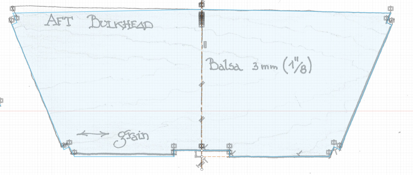
Here’s the most divergent example, the Aft Bulkhead. I think I did a decent job tracing the geometry on the right, but when I mirror it, it looks way off the hand drawings:
Here’s what I did:
- Eyeballed the vertical centre line, not constrained to vertical in CAD space
- Created the right side of the top line perpendicular to the centre line
- Eyeballed the right end of the top line
- Eyeballed the corner of the top right notch
- Created the bottom of the notch perpendicular to the left side, eyeballed its endpoint
- Eyeballed the right line to the bottom notch
- Eyeballed the corner of the bottom right notch
- Created the descending line of the bottom right notch as perpendicular to its top line
- Eyeballed the length of the bottom right notch
- Made a construction line from the bottom right to the centre line, perpendicular to the centre line
- Eyeballed the horizontal position of the notch at the bottom
- Drew a perpendicular line to the eyeballed height of the bottom notch
- Drew a perpendicular line from the top right corner of the bottom notch to the centre line, also perpendicular to the centre line
- Mirrored the geometry across the centre line
I guess I have a few questions specific to this part:
- Is the top line of the transom and bulkheads supposed to be straight?
- Given that the stringers are specified as 2mm x 5mm, should I be sizing the corner notches accordingly? My trace of the top right notch came out to 1.991mm x 3.715mm; should I expect to leave the 5mm stringers proud (perhaps helpful in aligning the deck?) or trim them flush with the topsides?
Thanks!