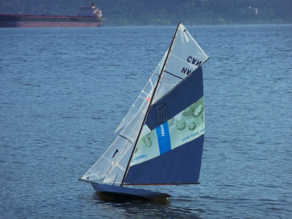
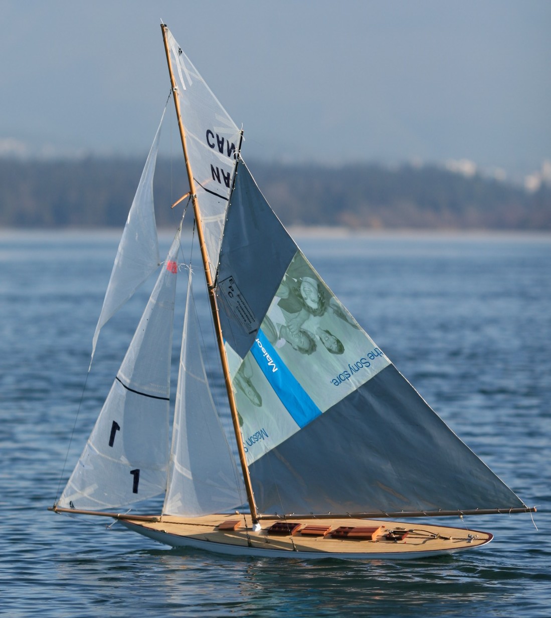
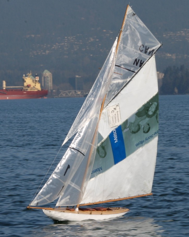
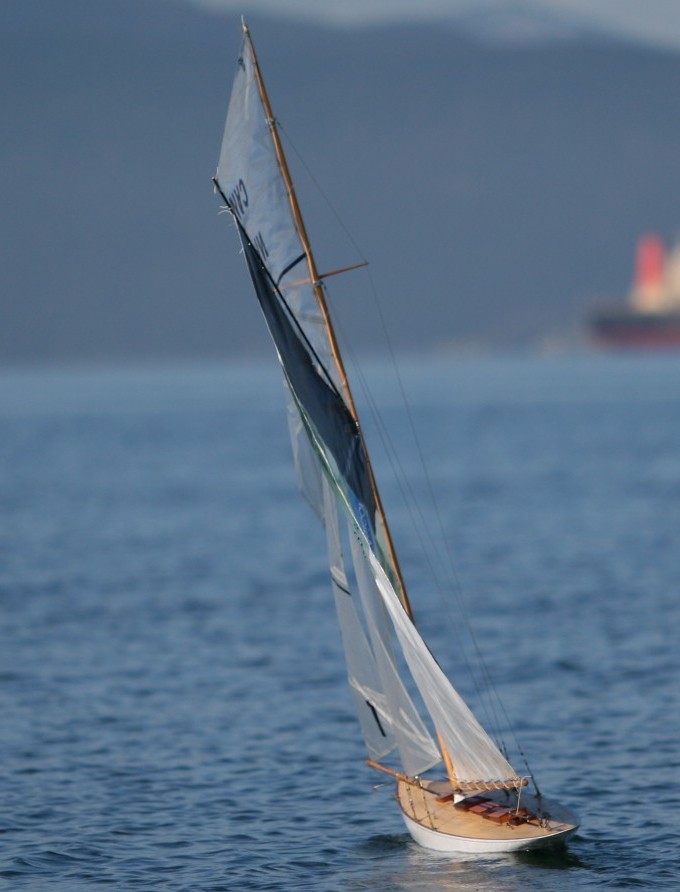
 Classic metre yacht designed by William Fife III
Baltic plywood frames, Canadian cedar planked, fiberglassed over cedar
Spektrum 5 radio unit.
Took over 1 year to design and build
Video
http://www.youtube.com/watch?v=I6XfaYPXjfo
kingplank
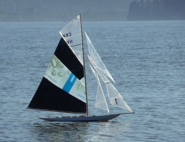
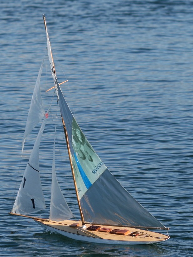
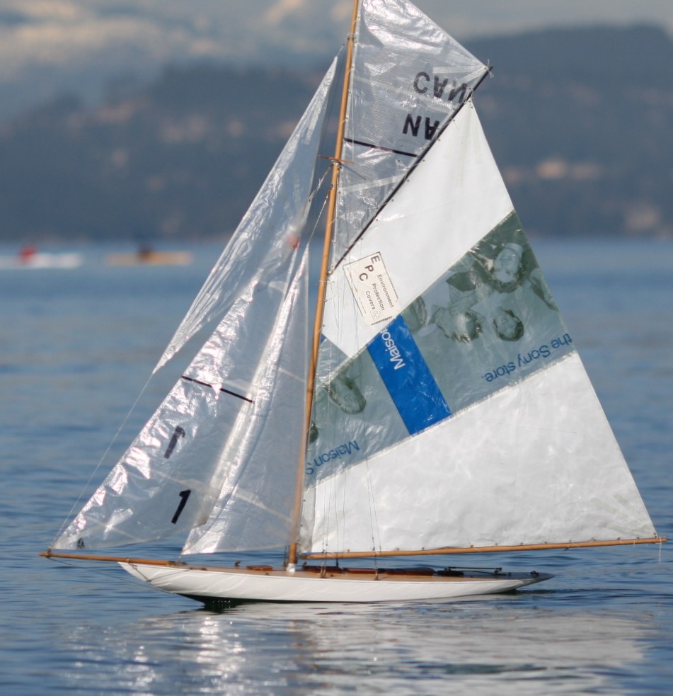
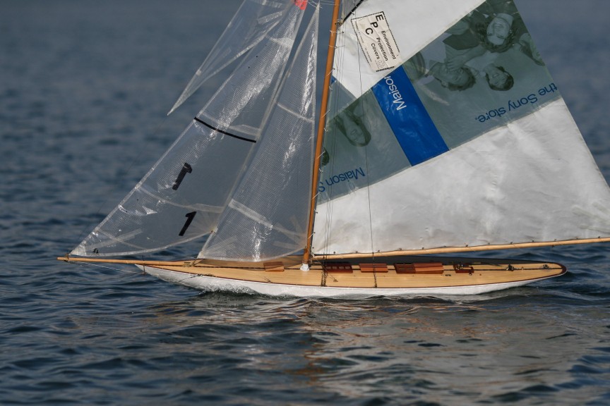
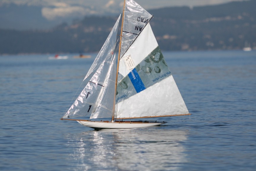
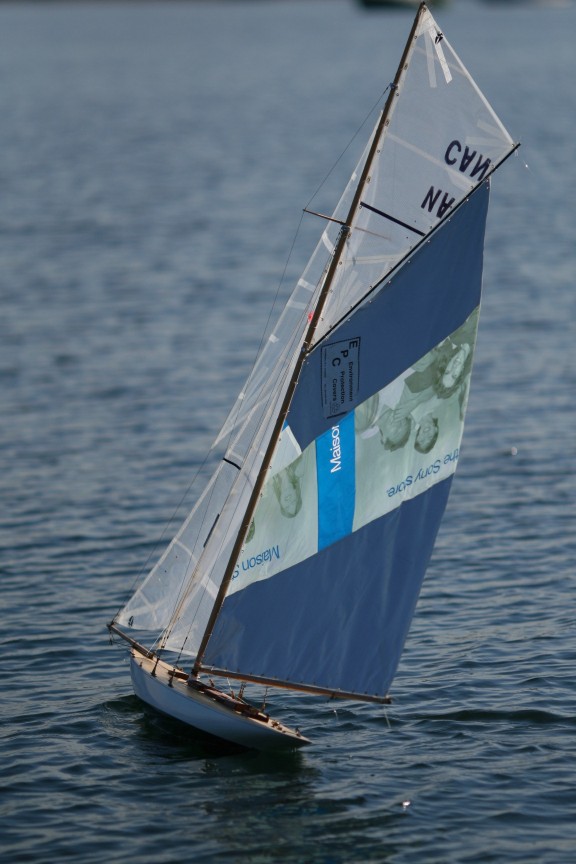
Classic metre yacht designed by William Fife III
Baltic plywood frames, Canadian cedar planked, fiberglassed over cedar
Spektrum 5 radio unit.
Took over 1 year to design and build
Video
http://www.youtube.com/watch?v=I6XfaYPXjfo
kingplank
Hi Kingplank
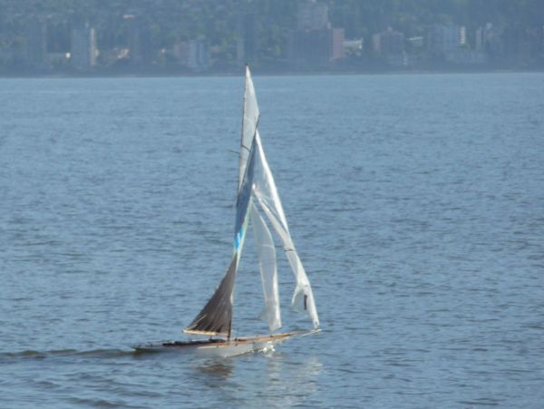
beautiful boat but what a pitty, no one single change of tack filmed ! Why ?
Cheers
Claudio
Claudio,
here are some more videos with change of tack
Enjoy!!
kingplank
http://www.youtube.com/watch?v=uhEapBUKdhI
Thanks a lot kingplank, that’s great !
I’m furthemore appreciate because I have under construction since 2 years the replica at 1/15 of another Fife design, the TUIGA that celebrated 100 years last September in Monaco.
When it will be finished ? I do not knows since I just started the Enterprise at 1/2 ‘J’ class drawings !
Here some pics of the model and of the real !
Cheers
Claudio
Hello Claudio,
I am very impressed with your block construction. I tried to buld them several times and failed. Ended up buying Pekabe instead.
Regards,
kingplank
Hi Gerard,
I have just finish to draw up the plans and shadows for the Enterprise at a scale of 1:28 that give a lenght of 131cm or 51.5 inches.
I wonder what type of sheet control I shall use for the 3 jibs. Have you any simple suggestion using only one servo for the jibs a one for the main ?
Thanks I will appreciate.
Cheers
Claudio
PS some draws in attachment
Hi Claudio,
I built a Fife 10 metre “Tonino” a few years ago; she is 1270mm, with 2 jib and gaff. All sheets are controled by on sail arm servo. I had over 200 hours of sailing with this boat.
She has very deep 350mm fin with 3.5 kg bulb. Because of the enormous sail area, she is very difficult to sail.
The Mariquita is also sheet controled by one servo, a Hitec sail winch. The top jib is fixed sheet As you can see in the videos, she sails quite nicely in light and mederate winds; and uncontrolable in big winds.
Ballast is 6kg, 350mm deep.
Your Enterprise plans are beautiful, will be a spectacular boat when you finish.
Regards,
Gerald “kingplank”
HI Gerard,
thanks for the answer.
It may be that at the end I will come up with a fixed sheet.
Actually my idea is to try to control the top jib as well the middle jib in a normal way with adjustable sheets - all 3 jibs controlled by one close-loop circuit and one servo.
If you have a circuit to propose I will be happy to see.
The top jib would be controlled by sheets coming from the fairlead close to the mast step and raising up to both extremes of the lower spreader.
The intermediate end lower jib sheets should get the fairleads close to mast to and reaching the deck line via rings or smal floating blocs.
The second option for the top jib is to adds a parallel rail/wire to the spreader and link the jib via a fix sheet and sliding ring.
Unfortunately, until now, I didn’t find any picture showing the real deck layout of the Enterprise. In spite of the fact that was the first winner of the “J” formula , this boat have little resonance in the press, probably the famous Wall Street crash was still in the mind of many people…
I just ordered the veneer , a blond/pink Alizé wood that I will use to ‘laminate’ the fiberglass hull.
The boat in facts, will be warnished wood , in practice will be coated with fiberglass and epoxy. Past experience using simple polyurhetane transparent paint revealed to be uncompatible with water, the strips of wood were swelling.
Cheers
Claudio
See Drawing & picture of my first class M in mahogany
Claudio,
my sheet works on the priciplal as yours.
Attachment ponts are closer to the sides of the boat, and furthur aft.
One side is actually fixed to the deck
regards,
Gerald
Hi Gerald,
I’m not so sure yet what solution to adopt for the fore sails. I will prepare a mockup to verify .
The other uncertainity is the bulb location, construct the keel as originally drawn and adding a detachable fin/bulb like your Mariquita or change the keel shape by make it deeper. Actually I tend to the additional fin/bulb like you did it.
By the way how deep is your fin from waterline ?
The pear tree veneer is just arrived.
I ordered the book “Enterprise to Endeavour” another one for my library.
François Chevalier is going to send me the deck layout.
Cheers
Claudio
Hi Claudio,
The Mariquita is 430mm from the waterline to the bottom of the bulb. For your boat, I would guess 350mm is ideal
I have tried very long keel on a classic boat ; but she will look right during sailing.
For locating the bulb, I usually tape it on a temporary fin and test it in the water to see if it is located correctly.
With all the weight in place, the static position I set the bow 10mm higher on the water line; because the bulb and fin usually force the bow down during sailing.
Fin location is usually at the therotical displacement centre.
I have just purchased a new book Classic Yachts by François Chevalier.very happly to see the lines plan of Cambria.
Cheers
Gerald
Thanks Gerald,
I was drawing total draft at 400mm, of course as you say I will test it first. The ballast will be in principle 62% of the displacement of 5.85kg
Cheers
Claudio
I’ve played around a bit with small scale models of J boats:
http://usvmyg.org/YankeeIII/YankeeIII.htm
and have a couple of suggestions that might help. In 1935 the Boucher Co. made a model of Shamrock to the M Class rules, 50" LOA, 800 sq in SA. Her draft was 19cm. With the higher ballast ratio of a fiberglass hull you may have too little volume in the fin for ballast, so you might consider making the fin thicker to give more space. An alternative to a bulb for external ballast is a “lead centerboard,” used frequently in the U.S. in the 1890s. This is a thick lead fin shaped like a centerboard in profile, which IMHO looks much better than a bulb in the water. As I’m sure you know, J’s and other Universal Rule boats were designed to sail rail down whenever possible, in order to stretch out on their sailing lines. Having too deep an external fin/bulb will make her too stiff and she won’t “look like a J.” Plus the bulb comes close to the surface when she heels and spoils the look (again, IMHO). Another trick is to trim her so she floats a little deeper than her waterline. This will improve her sailing and not be obvious because you should seldom see her upright  You’ll also probably not require such a large rudder. Despite the long keel, these boats turn very quickly; I surmise this is because of the rake on the rudder.
When John Black designed the free sailing Yankee Jr. in 1935 (the boat which I adapted to make Yankee III) he reduced the sail area to 90% of scale, and then increased the aspect ratio to fool the eye into thinking the rig was higher than it was. Another suggestion on loose-footed foresails: if you run a flexible batten from the clew to the luff, at right angles to the luff, then you can use a single sheet on the centerline and the sails will hold their shape.
Finally, for that bit of really obscure detail, I’m attaching a scan from a 1930 magazine of Harold Vanderbilt’s house flag, which flew from the masthead. The colors should be pure red, white and blue.
Good luck on your project and I know all of us can’t wait to see what she’ll look like on the water.
Cheers,
Earl
Hi Earl,
thank you for your suggestions, reconizing your competence in the matter.
I’m not totally sure to have all understood and because of that I drawn the attached file.
3 options :
1- use the original layout knowing that it may not work even increasing ballast and accepting deeper floating line
2- modify the keel shape in order to lower the ballast permantely - Aestecically I’m not totally happy
3- add a removable prothesis composed of fin and bulb - Aestically not very nice but efficient.
Oviously option 3 offer the higher righting arm , but it is much less aestetic once out of water until the fin/bulb are removed.
In all 3 options, the ratio displacement / ballast is kept constant - the ballast increase as the additional modifications change the overall volumes.
The Sail Plan will be around 80% of the real one scaled down
I would appreciate very much to receive comments from you and /or from modelers that already aquired that experience.
Thank to all in advance.
The materials are just arrived including the epoxy resin called “SurfClear” that is very transparent , excellent for the veneer I want to use.
Cheers
Claudio
Hi Claudio,
I disagree on adding more weight than the calculated displacement. I had too much weight on my Vanity V at the beginning; when she floated low on the waterline. Looked very ugly; and that is not what you want.
I am satisfied that these classic boats are only capable of light winds; that is why I am building the Safran 60 for big winds, big waves; and planing the waves.
Regards,
Gerald
Hi Gerald,
I do not add additional weight over the one necessary to keep the floating line.
The increased weight is simply due to the fact that di displacement increase by adding additional volume under water to the existing keel, in fact from 5.85kg the displacement increase to 6.15kg about and similarly by adding a fin/bulb, the volume underwater increase further.
The data are written in the drawing I presented. If you check carefully you will notice that the displacement/ballast ratio remain constant and the waterline also.
Cheers
Claudio
It’s funny that I never saw this post before. I to am a Fife Freak. This is my version of the 1903 Cicely. She is red cedar planked, the deck is yellow cedar planks, cabin and skylights are mahogany, spars are spruce and the sheer rail is walnut. The hull is supposed to be white but the planks looked so nice I couldn’t bear to paint them.
Don
Hi Don,
Your Cicely is absolutely georgous. I am also a huge Fife fan.
Here is a list of Fife yacht models that I built
They are all built for RC, but I have only 4 with rigs and radio fully completed
Gerald
Vancouver
Here’s my suggestion for Enterprise. This is based on Steve Kling and my experience in doing 36" models. I’ve designed and built Yankee, and designed a Whirlwind and a Ranger. Steve has built Whirlwind, Ranger, and gone on to design and build Endeavour II and the Tore Holm boat, which was only partially completed when WWII broke out.
The way we do this is to steepen the entry angle of the keel which reduces the amount of reverse curve on the leading edge when the keel is dropped. The real trick is making the fin thicker. This increases the displacement and ballast ratio, and permits more ballast forward of the CB. Note the full width at section “A.” Also, please excuse my sloppy drawing
Based on our experience, and 1935 Boucher Shamrock design, I think this hull will be able to carry a reasonable sail plan.
Speaking of sail plans, as I am again sure you know, one must not rely on the published sail areas for the J’s but rather do exact measurements of the sails. This is because the published numbers are the “rated area” by Universal Rule, which calculates the foresail area as 85% of the fore triangle rather than the actual area. This is why you’ll see some foresails described as, e.g., a “120% quad;” meaning that its actual area is 120% of the rated number.
Cheers,
Earl
Hi Gerald
You wouldn’t have the lines of the Lady Anne would you, or know where i could get them? I’ve wanted to build her for a long time and don’t know when I would get around to it but it would be nice to be ready when the urge becomes overwhelming. My reason for choosing her is that there is lots of detail pictures on the internet.
Thanks Don