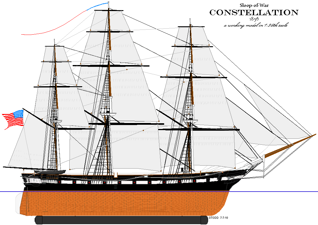
Sloop of War Constellation c.1856 in 1/36 RC

George, lowering the ballast on struts that way also gives the ballast the leverage it needs to open the hull like an oyster. Grab 50 pounds and hold it in front of you with your elbows at your sides and tell me how long it would be before the deck is sprung and the keel’s twisting out.

That doesn’t even address the idea of handling a 100 pound model with a spider’s web of sticks and strings on top and a 50 pound weight dangling a foot below it.

The SC&H model of HMS Surprise carries about 40 pds externally in the same manner I plan and the model’s almost exactly the same dimensions as mine except my rig is slightly shorter. My external weight will be 4" tall at 50 pounds, and 7-7.5" below the LWL.

Here’s a rough sail plan, that’s proportionally scale. The model’s dimensions are in an earlier post.

Here’s the hull with a wooden mock-up of the ballast keel attached.
The keel will be 48" x 3-1/2" x 3/4" and allowing for the rounded front end and some relief of the corners should weight in at about 50-1/2 pounds.

Well, a month later and here’s where things are:

A deck was put in for the battery to rest on. 4 Velcro tabs hold it in place.

Blocking was added in various places where the braces and jib sheets will pass through the deck.

Two 4 inch PVC female adapters and caps were cut down to become access hatches that will be disguised as pivot guns. :wink:

A mount for the rudder servo was made and installed on the mizzen deck.

A step for the bowsprit was framed and installed - today in fact.

And a great many brain cells have given their lives in the quest to figure out the bracing of the yards as it’s handled below decks.

Here some developments on the ship’s rudder.

The rudder is made of acrylic (Plexiglas). The 1/2" tube in the hull is filled with J.B.Weld (a two-part epoxy filler) with a 3/16" i.d. tube centered in it. The 3/16" rudder post slides into this tube. The woulden rudder head approximates the scale rudder head and serves as a stop against the JB Weld fill to prevent the rudder riding up. A gudgeon plate at the heel of the keel steadies the bottom of the rudder post.

Rudder nearing completion - just have to add the pintle straps.

Looking at various ways to handle the braces for the yards (spars the square sails hang from), by all sorts of modelers, I’ve decided to go with a direct winch set-up.

All the lower yards will be controlled by braces as well as the topsail yards (second from bottom) of the fore and main masts (front and middle) - 5 in all. The ones above that will be handled in a future episode. :wink:

All the braces will be doubled aloft - that is, they will be attached to a fixed point, run to a block (pulley) at the end of the yard and back to a block fixed in the rigging, then down, through the deck where it will turn forward to a block on a spring mounted on a post. From here it goes through a fairlead and onto the winch.

With the yards square across the boat and the braces snug, there comes a geometry problem when you turn the yards. The brace runs from some fixed point to the end of the yard. As it turns, the tip of the yard moves in an arc, but at any given point in it’s travel the brace is a straight line from the fixed point to the end of the yard. If you charted the length of the brace at every couple of degrees, you’d get something like a sine wave pattern.

Using a circle (winch drum) to handle the braces means the brace with tension and slack at various points as the yard turns. THAT is why there are going to be blocks on springs mounted on a post inside the model. The springs will take up the slack, and give to the tension like a shock absorber - keeping the braces taught and preventing snags or the line from falling off the winch.

There’s various ways of doing this. weights, bungee, specially shaped spools (in that mentioned sine wave), and other set-up that don’t use braces at all. I happened on a box of assorted springs for $5, so it’s springs for me. :slight_smile:

The image (con072509c) with the servos is looking forward and shows the two posts the spring will be mounted on. They fit into sockets on the deck beam up top, and will have a set screw at the bottom allowing for removal if need be.

The image with the disks (con072509p) is looking aft and shows initial mock-ups of the winch drums. The flanges will be 5 inches with the largest drum surface for the main yard being 4"

The cut-away drawing shows the general routing of the braces. Only one side’s braces are shown.

Fascinating thread. Keep up the good work.

John

With the method of bracing determined, it comes down to setting it up.

The posts that carry the springs were moved out-board of their original position to help keep down the clutter below. The springs were also move higher on the posts to better line up the braces with the disk, cutting down friction on the fairleads. A deck beam had to be removed to allow me to get a drill inside to make the holes in the servo deck beam for the threaded inserts. With these installed, the deck beam was replaced and the posts now held in place by stainless socket head screws.

A bit of CDX 5/16 ply prepainted and left-over from another project was used as a platform, or tray, for the servos. The servos are held by 8/32 stainless machine screws into brass threaded inserts in the plywood. The fore mast winch is mounted about 1-1/2 inches higher so the disk stacks will overlap and to keep the braces from interfering with each other.

The disk stacks will be just that. The drum portions will be styrene built up to the correct diameter with flanges made from old compact disks. 11 CDs will be sacrificed to become two reels for my brace winches.

The brace line will pass through a hole in the drum and be fixed to the top with a screw/washer - something my fat fingers can handle. :slight_smile:

The stack of disks that are the winch drums are made of alternating disks of wood and compact-discs (CDs). The wood disks are the “drums” and the CDs serve as flanges.

The wood is scrap, resawn on the bandsaw then run through the planer till it’s 1/8" (3mm) thick. A square is cut to size, the center found, and then it’s cut into a circle on the band saw using a simple jig. Each wooden disk had a 1mm slot cut from the rim to the center to allow the brace line to be threaded into it later.

The CDs had a raised ridge on the write side that was sanded off. They were old game CDs, so I had to sand off some paint where glue was going to go.

I put a nail in a board, cut the head off, and stacked alternating CDs and wood disks on it with the slots in the wood disks all lined up together. The nail acted as a spindle and kept the wood disks lined up as I glued the stack together. The CDs I lined up by eye. The important thing here is that the rim of the wood disk is tight to the CD on either side so there’s no gap for the line to get wedged into. The glued up stack stands about 1-1/8" (29mm) tall.

To allow access to the screw that will hold it to the winch servo, and the lines threaded through it to it’s center, a 1" (25mm) hole was bored down the stack’s center. The stack was clamped between two boards and that was clamped to the drill press table. A 1" Forstner bit was used to get a clean hole. I think a spade or paddle bit may have torn up the mixed material layer cake. I drilled a little, raised and cleaned off the bit, and drilled a little more to keep down the heat, which would melt the plastic of the CDs.

Three pan-head sheet metal screws were sunk around the center in pre-drilled holes to reinforce the glue holding the stack together. They were 2" long, and I cut off the excess. Machine bolts would have been better for this, but I didn’t have any.

The red servo horn that came with my rudder servo was attached to the bottom of the stack with 4 3/4" (19mm) pan-head sheet metal screws. Besides holding the horn on, they reinforce the stack from the bottom the way a nut on a bolt would have.

I used a bit of wire to clear the slots in the wooden disks and made sure I could get lines through them. Then I attached the stack to the winch and strung up a line to give it a try.

Now! - all that said and done: The largest drum is 4" (10cm) is diameter and meant to haul in about 40" (102cm) of line over it’s full travel. The bigger the disk, the more leverage it has on the winch. HiTec says NOT to increase the drum size from the one that comes with the winch for that very reason - SO, if you burn up your winch servo following a fool - it’s your own problem - understand?

Furthermore, the stack is tall and the lines pulling on it make it want to teeter and cant. I’m probably going to need some sort of bracing at the tops of the drums to combat that - stay tuned to see where that goes.

Some wiring done to fix what turned out to be a faulty DPDT switch and applied pintle straps to the rudder.

Other (paying) projects demand attention drawing time from this one, but I still managed to get somethig done…

Casting a lead keel’s been dropped. It’s been so wet here this summer I don’t feel safe casting in the ground, and a 50 pound pour isn’t happening any other way - so I opted to pour my lead bird shot into a 4 foot by 2 inch diameter PVC pipe. This thing weights about 47 pounds and should do the job. (see pics)

Next, a heel plate was a-fixed to the keel. Morticed in, epoxied to be waterproof, and tapped to receive a pair of brass machine screws that will hold the rudder’s gudgeon plate. This will allow the plate to be easily removed to service the rudder without a hole in the plywood keel for water to get into and cause rot.

The aim right now is to get the hull ready for it’s first launch and test float.

I started framing her head, which will be planked and enclosed.

On October 4th she got her first taste of water…

and she floats! More importantly, she doesn’t leak - not a drop!

Float-test one was without the external ballast attached. It wasn’t intended that way, it just happened that way.

Float-test two will include the external ballast and some extra weight in bags to see just what it will take to put her on her waterline.

Stay tuned.

Back down to the creek, this time with the rods to attach the ballast, the model went in to the water again.

Her battery, servos, and running gear, along with maybe 5 pounds of tools, and she still floats two+ inches high and will need maybe another 10 pounds of additional ballast.

Here it is January of a new decade already!

Constellation, and vessels of her time, had an enclosed head as opposed to the open decorative head ships of earlier times had.

The head area on the model is being enclosed pretty much the way the actual ship’s is; framed and planked.

The quarter galleries got some detailing as well.

Both end of the ship have more details to add, and a few yards of molding before the hull will finally get painted and start looking like what it’s meant to be.

Added some molding details bow and stern over the weekend.

Tracing the stern and noting the port positions and where the quarter galleries end, I scanned the tracing into the PC and laid out the molding lines with MS Paint (real high tech stuff here!) based on the image of the ship in dry-dock in Boston c.1859.

The moldings are bass wood and epoxied onto the fiberglass hull - waterproof carpenters glue where wood meets wood.

So far the stern moldings are applied, the moldings on the enclosed head, and the pilasters and mullions on the quarter galleries - which are not permanently attached yet.

The stern ports will be cut out and seal inside the hull to provide depth. In the 59 image, you can see they had split port-lids and I want to portray the ship with those ports opened.

The broadside gun-ports will also get this treatment. The ports with molded in details will be cast in resin and glued into the gun ports.

All the gun ports were cut out all the way around the hull. I was able to remove the outer glass layer and the wood behind it, leaving the mat layer inside, so I won’t need to install backing for the cast resin gun ports.

The gun ports will be cast from resin with all the details; gun muzzle, hinges, light ports, etc, molded in - then epoxied into the ports. Much easier than detailing each and every gun port individually.

The stern ports and the port just forward of the quarter galleries, will be modeled in the open position as these are actually used as windows. The two forward-most on either side won’t have gun muzzles modeled into their port lids.

I cast the gunless ports for the two forward most ports on each side by stamping a master into clay and pouring in casting resin.

The gun barrel and tampion (plug) will be added to the master to make the 20 ports where the guns are mounted.

All of these will be epoxied into the ports cut out previously.

I know they look like white chocolate - but I promise they don’t taste like that. :wink:

Cast 20 gunports with gun muzzles and tampions, and 4 new plain ports with more detail than the original set.

I originally was going to use muslin for Constellation’s sails. Muslin looks like scale canvas in weight, texture, and color. The problem is it’s a natural fiber and with out door use wouldn’t last too long. Salt and UV would weaken it and it would tear very easily.

The SC&H company supplies sails for their large RC model kits made of Dupont Supplex nylon. Several people I know with these kits swear by this material that’s strong, light, UV resistant, and waterproof. It’s made for out-door apparel; wind breakers, winter wear, etc.

So, I got two yards of it for about $12 USD to make Constellation’s 2,807 square inches of sail area in 17 sails!

All the sails are rough cut and the panel seam marked on with a .03 permanent marker pen. Sewing these seams would cause crinkling and puckering along the stiches spoiling the scale appearance I want.

The headsails are hemmed, and the largest of these, the jib, and the mizzen topsail have bolt ropes sewn on. The mizzen topsail also has reef point strips and “tabling” glued on with Liquid Stitch. The glue is doing a great job after having the topsail through the washing machine several times with no signs of failing, and it’s saved a great deal of difficult sewing and all the associated puckering mentioned above.

Supplex, unlike muslin, is a synthetic and therefore melts when burned. This property is very handy when making holes for reef-points, jib hanks, bonnet lacing, and the like. A quick touch with the point of my soldering iron makes a nice hole that’s sealed and won’t tear. Still, any place such holes will go ought to be at least two cloth layers thick to prevent pulling the weave of the cloth.

When sewing on the bolt ropes I used nylon twisted lines in the diameter I wanted. I ran about 2 inches of glue along the edge of the sail and sewed to the end of it, then glued another 2 inches, etc. It’s sewn on with polyester thread. The boltrope is not attached to the edge of the sail, but to the “back side” of it along the edge. The needle is passed through the sail close to the edge and through the bolt-rope, around to the back of the sail, about 3/16" further along in this case, and back into the sail and the the rope so the diagonal leg of the stich lays in the strands of the bolt-rope. The pictures should show what I mean. This is, in fact, how a bolt-rope is sewn to a real sail, only with stitches that are closer together.

The sail is held at one end by a clamp-on vice. A line with a weight (I used a pair of scissors) at one end, and a clothespin at the other end is attached to the other end of the side of the sail being worked opposite the vice - to keep everything under some tension - this makes it much easier.

At 1:36 scale, the absence of bolt-ropes on the sails would have been quite obvious - especially to an old nit-piker like me.
HI Jerry,

Although I am not a scale builder, I am enjoying your thread. Keep up the great work.

John