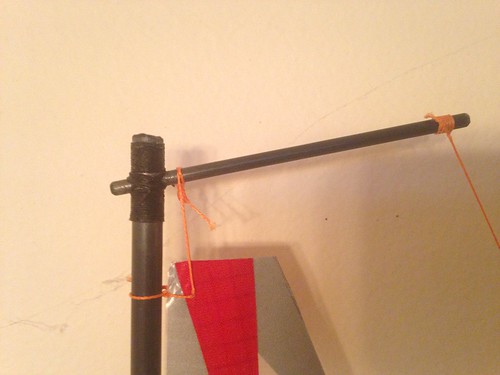
That’s the mast crane.
Those bolts are M3 for size reference.
Tubes are flexible, rods are much stiffer (rod=no air inside, just full of carbon fiber+resin).
My mast crane, about 8cm long, almost no bend:
Coolest:)
Do you use a jig to stop the drill bit slipping off the sides at all?
First, mast is hollow - not good for drilling. So start by finding a CF rod that fits exactly inside mast: cut a 5cm piece, slightly sand its length (improves grip), soak it with epoxy, slide into top mast end, clean end with cloth, and leave some hours to cure.
Then put mast on a holding jig - I use some pieces of wood. Start hole with a knife, making a small notch with knife tip. Use this notch to drill with a very small bit (1mm) first, slowly through whole diameter. Use this hole to guide successive slightly bigger bits: 1.5mm, 2mm, 2.5mm, finally 3mm. But don’t drill through from one side: do it first halfway from one side, then halfway from other side. This way you prevent splinter. Also, use fastest possible speed, and drill slowly.
When hole is ready, put crane rod in, adding lots of liquid CA (should fill everything inside, to keep CF together). Clean with cloth before it is dry.
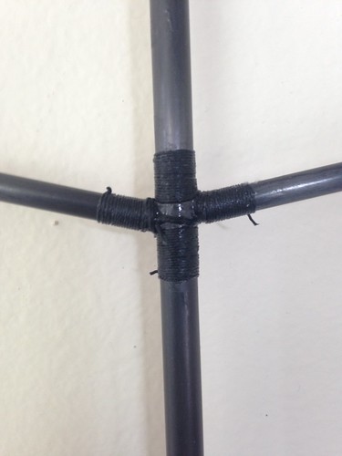
Finally, use some strong synthetic string that has no slack (same dyneema I use for sheets, just different color), and wrap around mast (again, to prevent splintering). Finally soak everything in CA, clean with cloth before it is dry. This is key to reinforce the whole thing - prevents CF from splintering.
I’ve used this in all my rigs, including a C rig with 30+ knots, no problems at all!
BTW, I use same technique for boom attachment - only difference I don’t use a CF rod through mast, but a stainless steel rod that fits into booms. Also, in this case booms need to be wrapped, too:
OK,
Cad pictures of the appendages…
Bulb is naca63012
KeelFin is naca63010 with 60mm at the top and 45mm at the bottom - Internet ninja reading points at that being a bit on the thicker side but I wanted to go for something a bit beefier as it’s my first attempt at this type of thing.
I continued the 60mm shape up into the keelfin trunk area and then sliced the back off to create the angle to lock the fin into the trunk. I did that so I have that profile up against the hull no matter how deep or shallow the fin sits into the trunk (I hope that makes sense)
Rudder is naca 0012 30mm at the top and 20mm just before the taper. I pulled in the original picture and cut the shape to match the hull lines but I’m sure I’ll need to tweak that a bit.
I had to manually create the taper on the end so it’s a bit ugly but I can look into that again.
The moulds are going to be cut out of 12mm MDF by my brother on his cnc machine. He often uses this method and reckons its a great way to make low volume, good quality moulds quickly.
On foils - take this as the layman’s understanding and hopefully it helps clarify it for some others like myself. It’s overly simplified but I believe the basic understanding is correct.
You’re swimming behind your yacht underwater. It is going dead straight with no heeling at all.
The water gets “sliced” by your keelfin and rudder and it flows equally around the left and right of the foils beautifully. Think of those smoke trails coming off the back of a supercar in a wind tunnel.
At this point the only consideration about the foil shape is how smoothly the shape parts the water and its drag (I’m sure lift is in there somewhere too but I’m still grappling that concept a bit:confused:)
Now imagine you turn the rudder hard left. It now no longer has a nice thin shape facing the flow.
This acts as a brake ( again, think of the air brake on super cars) BUT it also causes turbulence/ cavitation around it and the water separates from the surface of the rudder (think about the crappy airflow out the back of a large truck going past) and stalls (stops working like when your car aquaplanes - you can turn the steering wheel but nothing happens)
That’s the crux of the airfoils…
4 digit NACA foils (NACA0010 etc.) may not have the best characteristic for the first scenario where you’re going dead straight, but they let you turn your rudder further before you get a gradual seperation of the water from the rudder before stalling.
The other commonly quoted foils (NACA63 and 64) have better characteristics for the first scenario but will tend to perform comparably as you start to turn the rudder (increase the angle of attack) but will then suddenly cause seperation and stall the flow radically.
So you can use the NACA 4 digit ones(NACA0010 etc.) or the 6digit ones (NACA 63012a etc) for keels and rudders, but you are better off sticking to the 4 digit ones for your rudders as they are more forgiving at higher angles of attack - or put into my slang - don’t freak out as much when you ram the rudder hard left or right (which is a bad thing I know)
The bulb…
OK, my method has been kind of round-about but here’s how I got the thing done.
There was quite a bit of awesome info on the Groups website (am I allowed to link to other forums?) in a bulb thread - and as per the above rationale I had decided to build the keelfin using the 6 digit Naca63a010 profile from here
http://airfoiltools.com/search/index?m[grp]=naca6&m[sort]=1
So I figured I would use the same basic shape for the bulb.
So I have the shape and the weight I need to create the bulb, but I wanted to have a slot that the fin will fit into which will drop the weight of the bulb. I also need to think about the lead cooling and shrinking by about 1.5%.
So I put together a little spread sheet to take all of this into account (See attached file) and used it to adjust my goal weight in the Calculater by extending the length of the bulb. (You could also change to a different profile too)
You could then print out from there directly and build a plug manually… however I’m an idiot who likes doing things the long way cause I can so
Thanks to the bulb calculater I now had my length and profile locked down.
I used the airfoil tools link to create profiles and export the co-ordinates for FreeCad. You can do this via the Bulb calculater but I had an issue that Freecad imports in mm and the calculater supplies it in cm so I had to manually move the decimal point. The airfoil plotter exports in mm so it was far easier.
There was a bit of fiddling required to get them into Freecad but I’ll do a little write up/walk-through in a separate thread.
Behold…
and then sliced into little sections
I went this way of cutting them as the printers give way better resolution going vertically rather than horizontally on this sort of shape.
The bits printed and glued.
I need to do some clean up but I’m pretty chuffed. Still learning the printer though 
Here’s a dud and the second attempt with less heat and lower speed.
There should be an attachment called “lead maths.zip”
Thats’ got my little spreadsheet in old XLS and OpenOffice format. Lets you punch in the original desired weight, amount of shrinkage you expect and define a block slot size. It then takes the slot volume and adds it to the bulb weight to give the new weight you should be aiming for.
Just keep in mind, that regardless of the NACA foil shape and the theory of your above notes, if you “SLAM” your rudder over hard, regardless of the shape and theory you WILL stall out the hull, and possibly cause a loss of air over the surface of your sails if you do it in light wind. Thus the reason many will suggest a lot of stick time and having a “quiet” thumb on the stick, making slow and gradual rudder movements to retain the hull speed, and keep flow attached to your rudder. When racing my beach catamaran, and approaching the line a bit early at the start, by force full, large and fast rudder movements, I could virtually stop dead and hold until the gun. The ability was aided by lack of lead (keel) and momentum in a light boat - but the trade-off (as in most things) was that I wasn’t moving very fast at the gun, having to wait for wind to reattach to sail, and water to dagger boards. Once you get on the water, experiment with the reaction to rudder movements and keep then in mind once in the heat of racing.
Cheers
Hi all,
just my two cents about the Stall for a NACA 0010 / 0012 with 40mm chord
This figure represents a rudder at 12° that according to foils specifications is the starting limit to enter the Stall condition.
Many do not realize how it is easy to create a Stall.
Cheers
Claudio
Oh yes: move the rudder smoothly, don’t ever hit it or release it hard! Move it the stick a little bit: only after the boat starts turning, you can move it another bit… wait for the boat to turn a little faster, then move the stick another bit… then before you reach the new direction, start releasing… again slowly…
Practice makes master.
Thanks Claudio
Is my basic understanding correct though?
Where do you find the info about the stall angles and what are the reynolds numbers our yachts use? I am starting to understand the concept of the Reynolds numbers but I’m a bit confused about where we sit.
Here is the bulb’s progression over Saturday. It’s looking pretty good so far. If anyone tries to print a bulb like this, then don’t bother with the little rods sticking out the ends. They keep snapping off 
Next time I will make the 3d model with a hole straight through so I can use a carbon rod as an alignment tool and then it will be less likely to keep snapping off.
Thanks for always popping in and adding ![]()
Guys, if you have the sail and bulb’s COE etc. aligned correctly, will you still need some rudder to maintain a straight course? I reworked the Apsara and it’s running far smoother but I always got weather helm that needed a bit of correction. this got progressivley worse in heavier gusts. Is that normal?
Just curious, but how long did it take to print the bulb plug?
I am thinking about pulling out my wood lathe and trying a plug from wood.
Thanks, Dick
Hi Dick.
My printer is new, it’s cheap and I’m learning how to operate it properly so I ran it extremely slowly.
It took about 2 1/2 hours to print in total, then I had to sand it down etc. which I’m sure was more work than a piece coming off a lathe would have been. I’ve never had the opportunity to use a lathe but I would assume that it’s quicker by far with less finishing work needed.
Thanks for info. What did you use to calculate your bulb weight and shape?
My grandson built his own 3d printer, but is off to college now. (Electrical engineering at North Dakota State University) but wants to build a CNC router this summer. (I get to finance the thing). so am keeping my eyes open for software or tables to provide initial input data.
Dick
Hi, Naphtalene
yes, this is normal.
Assume the boat is in perfect balance when sailing upright.
Now heel the boat. CE of the sails is moving sidewards out of the midship line which will introduce a torque to windward (force is pointing forward).
Simultaneously the CE of the keel is moving also sidewards (to windward). The drag of fin and bulb will increase this torque (force is pointing backward).
The effect becomes worse when heeling more because forces and lever are increasing.
In addition most hulls are getting asymmetric when heeling, causing an additional torque to windward.
This is why in gust you let go the mainsheet a bit, but keeping the jib tight.
Hi,
Thanks for the confirmation and explanation on the helm issue 
Dick, there is a fantastic site I just found http://openbuilds.org/ they have builds and give all the info on what electronics etc. they are running.
There are awesome builds that are mostly based around Aluminium profiles so the structural integrity/tolerences are very good. Theres a small one called “ThePlater” that is a scaled down version of a bigger version. Looks awesome.
RE the bulb weight… I used the bulb calculater and then transferred that into an online shape calclulater etc. I have almost finished putting together a “how I did it step by step” guide. I’ll post it up soon
Thanks, forwarded the web URL to my grandson (now in college) to see if I can prompt him into building me a CNC that uses router. If we can get that working perhaps I’[ll look to laser for cutting bulk head templates and such.
Also will look forward to your instructions for building when it is posted.
Dick
Ok, finally started prepping to pour a plaster mould of the bulb.
I will update once it’s completed and see if it comes out at the projected weight.
I am also one year into building and that’s a bit ridiculous. I am hoping to get going on the mould of the plug shortly too.
Lots of talk and no pictures/progress at this point 
Good news!!!
I got the calculations a bit out but never the less, a bulb made by me for me 
This is before I have cut the slot for the keelfin so I will be under weight, however I’m very happy with the result and can now work non refining the process.
The mould is straight plaster of paris. It worked out well as I discovered that if you don’t have air holes then you can’t pour in the lead lol.
So I just grabbed an old screwdriver and carved those angular slots into the bottom half of the mould. I did three failed attempts where the bulb got halfway up and then the air block formed so I slowly added more.
Lessons learned so far…
Pour hole must be on the mould split line.
On my next attempt I’ll put the pour hole lower than the the highest point of the form, and then vent from the highest point. That way the lead should be able fill all the way smoothly.
Since this worked pretty well I’ll do the write up on how I got the bulb shape/weights and pluged it into the Cad app for anyone who wants do do it themselves
Oops, forgot to do the write up:(
Been busy getting this done…
I have printed a test mould to see if it is a viable technique for rudders and fins and I believe it shall be awesome. Here’s the test single half from abs. I got warping which I’ll address but you can see in the second pic that I got a very nice foil shape with my test fiberglass layup. It’s 3x layers of that very fine surface tissue stuff as practice before I attempt the real thing
I printed it at .1mm layer height and the finish was way better than I thought it would be. It would be a fairly simple bit of sanding to get it up to a gloss.
It was recommended to try put a foam core in when I do a proper attempt at a layup so that is the next step. Print both halves of the mould with the revised rudder planform ( simpler shape for me to try layup) and to put a core in. Then onto the keel attempt… pretty scared for that one lol